PM20 Power Monitor Install Guide
Summary
We will walk through how to install the Samsara PM20.
Note as of 2/1/2021: We no longer sell PM20s. See below for what we recommend for Power Monitors:
Power Monitor recommendation:
Current Transformers recommendation - 5A secondary:
PM20 Power Monitor Introduction
Samsara Power Monitors captures fine-grained electrical power usage to analyze consumption, measure efficiency, and reduce operating cost. PMs are ideal for instrumenting pumps, compressors, motors, and other power-intensive equipment. Samsara’s cloud-based software, includes live remote visibility from any web browser, real-time SMS and email alerts, and historical graphs and data archive with unlimited storage.
A power monitor system consists of one or several current transformers, a power monitor, and a Samsara Gateway.
The basic system configuration has the current transformer reducing the current of the line and sending it into the power monitor. The power monitor then sends information over RS485 to the IG.
Datasheets and Install Guides
Go to All Datasheets and Install Guides and search for DIO Module. |
|---|
PM20 Power Monitor Installation Steps
Activate the Device
Once you unbox the Power Monitor, find the serial number. The serial number can be found on the backside of the box or on the back of the Power Monitor. Go to the Samsara Cloud and activate the device:
Activate Device(s) in the Cloud
Power up and Install the IG
Follow the instructions to power up and install the IG that will connect to the Power Monitor:
Prepare for the Installation
Safety Precautions
Electrical equipment should be installed, operated, serviced, and maintained only by qualified personnel. No responsibility is assumed by Samsara for any consequences arising out of the use of this material. Turn off all power supplying the equipment before performing the installation.
Required Materials
|
|
Current Tranformers Samsara Sells
Name | SKU |
400 Amp Current Transformer | ACC-CT-400A |
200 Amp Current Transformer | ACC-CT-200A |
3000 Amp Current Transformer | ACC-CT-3000A |
800 Amp Current Transformer | ACC-CT-800A |
1500 Amp Current Transformer | ACC-CT-1500A |
How to know which Current Transformers you need
Know the max current that circuit is going to use and what the configuration of voltage and wires is. Voltage can be 110V, 220V, or 480V in single phase or three phase.
Note: You will also need 2 to 4 wires (depending on the phase and ground configuration).
Installation Setup
The physical setup involves attaching a current transformer to a leg (or multiple legs for 3 phase) of the line power that is to be monitored, and attaching that current transformer to the corresponding power monitor.
The line voltage also needs to be wired to the power monitor. It calculates power by multiplying current times voltage.
Multiple power monitors can be connected to the same RS485 bus and eventually terminated at a USB to RS485 Converter, which is then plugged into the USB port in the IG21.
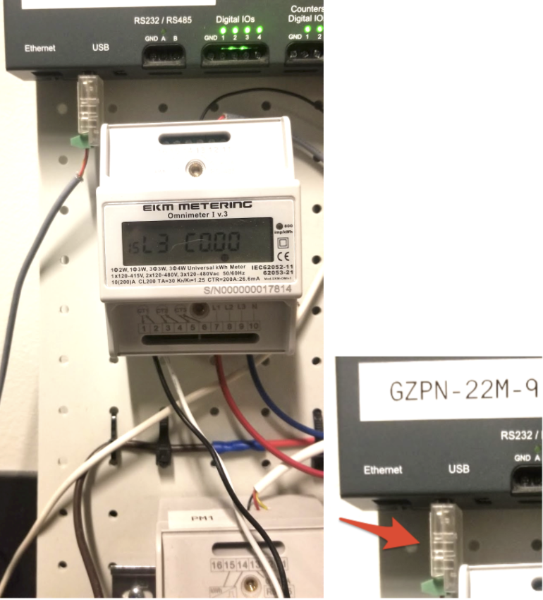
See the picture below of the current transformers on the left and power monitor with the RS485 to USB converter in the IG21 on the right. You will need to make sure you have a USB for each gateway. We recommend: BTE17-07 CH340E USB to TTL (link here for example).
Install the PM20 Power Monitor
1. Turn Off Power
Disconnect or switch power off before attempting to install, connect, disconnect or service the power meter or the external current transformers (CTs). ALL POWER MUST BE DISCONNECTED!
2. Determine System Type
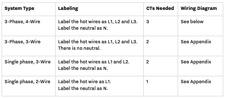
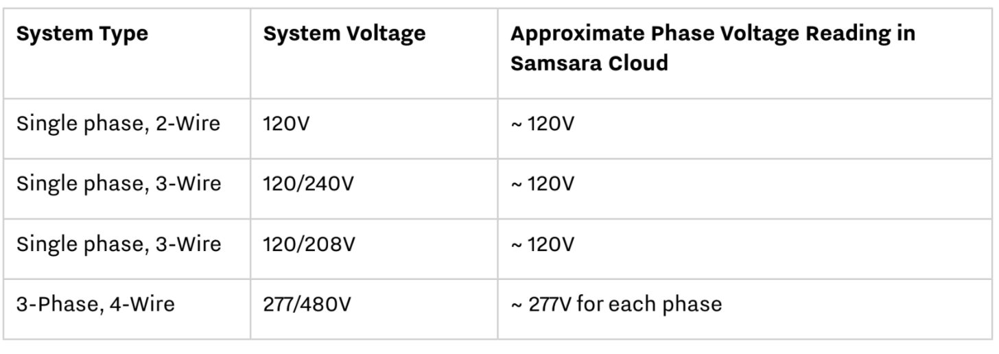
Identify how many wires are in the system and determine which are load and neutral. Load, or hot, wires are usually red or black. Neutral wires are usually white. Verify with a voltmeter by measuring the voltage between the wires and the ground. Distinguish and then identify the neutral and hot line(s). Label the neutral and then hot wire(s). See the table below for how to label the wires for different systems.
3. Connect Power Meter
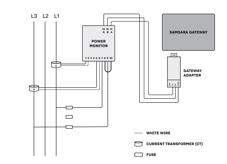
3-Phase 4-Wire Power Monitoring Wiring for up to 480V
Wire the CT1, CT2, and CT3 to ports 1-6 on the power meter respectively. Connect black wires to ports 1,3,5 and white wires to ports 2,4,6. Must be completed BEFORE connecting CTs to L1, L2, and L3 hot wires.
Connect the CT1 so that the L1 hot wire passes through it and the arrow on the CT points towards the load. Repeat for CT2, and CT3 respectively. Ensure all CTs are oriented with the arrow pointing towards the load.
Connect the L1, L2, L3 hot line voltage reference wire to port 7,8,9 on the power meter.
Connect the neutral line voltage reference wire to port 10 on the power meter.

120V-480V, 3-Phase, 4-Wire
Label L1, L2 and L3. (Arbitrarily assign labels.)
You will be using 3 CTs for this install. Label them CT1, CT2 and CT3.
Fit CT1 around L1. Make sure the arrow is facing towards the load (in the direction of flow).
Fit CT2 around L2.
Fit CT3 around L3.
Black wire from CT1 connects to Port 1 on the Samsara Power Meter. White wire from CT1 connects to Port 2.
Black wire from CT2 connects to Port 3 on the Samsara Power Meter. White wire from CT2 connects to Port 4.
Black wire from CT3 connects to Port 5 on the Samsara Power Meter. White wire from CT3 connects to Port 6.
With split core CTs, close the CT around the wire to be measured and press firmly until you feel and hear it click to indicate full closure. The buttons should be fully out. Use a zip tie to ensure the CTs remain securely closed.
Use a max 1.0 Amp inline fuse on each line to protect the meter.
To power the meter and get a voltage reference: Tap into L1 at the breaker panel. Connect one fuse holder pigtail to the breaker, lug or an appropriate line-tap device, and connect the other pigtail to 16-22 AWG UL rated stranded copper wire for connection to the meter. L1 connects to Port 7. Tap into L2 and L3 and repeat the connection process. L2 connects to Port 8. L3 connects to Port 9. Neutral connects to Port 10.
Once the meter is properly mounted to the DIN Rail or enclosure and all wiring is completed, with terminal block covers installed, power can be turned back on.
Meter will then begin cycling through meter values.
Check out the Appendix for more options in Wiring.
4. Wire Power Meter to Gateway Adapter
Wire ports 11,12, and 13 on the power meter to the gateway adapter, and plug it into the gateway. Use 22/3 or 22/4 shielded wire.
Connect port 11 (A) on the power meter to A on the gateway adapter.
Connect port 12 (B) on the power meter to B- on the adapter.
Connect port 13 (G) on the power meter to GND on the adapter.
5. Connect Gateway to Power and Turn Power On
Once the meter is properly mounted to the DIN Rail or enclosure, all wiring is completed, and terminal block covers are installed, power can be turned back on.
With power back on, the gateway will automatically connect to the cloud via its cellular connection and update to the latest software. The LED indicates the gateway status. Confirm that the gateway LED turns green.
Gateway lights:
Solid Orange: The gateway is booting up
Blinking Orange: The gateway is attempting to establish a secure cellular or WiFi connection
Solid Green: The gateway is securely connected to the cloud
Check PM20 Power Monitor Connectivity
Log in to the Samsara Cloud and go to Settings (gear icon on the bottom left)
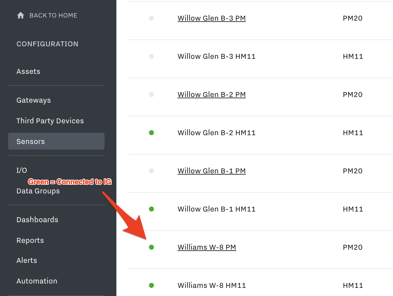
Navigate to Sensors on the left side navigation
Find the PM20 and ensure it has a green dot to the left of it in the Cloud
Verify Power measurements in the Cloud
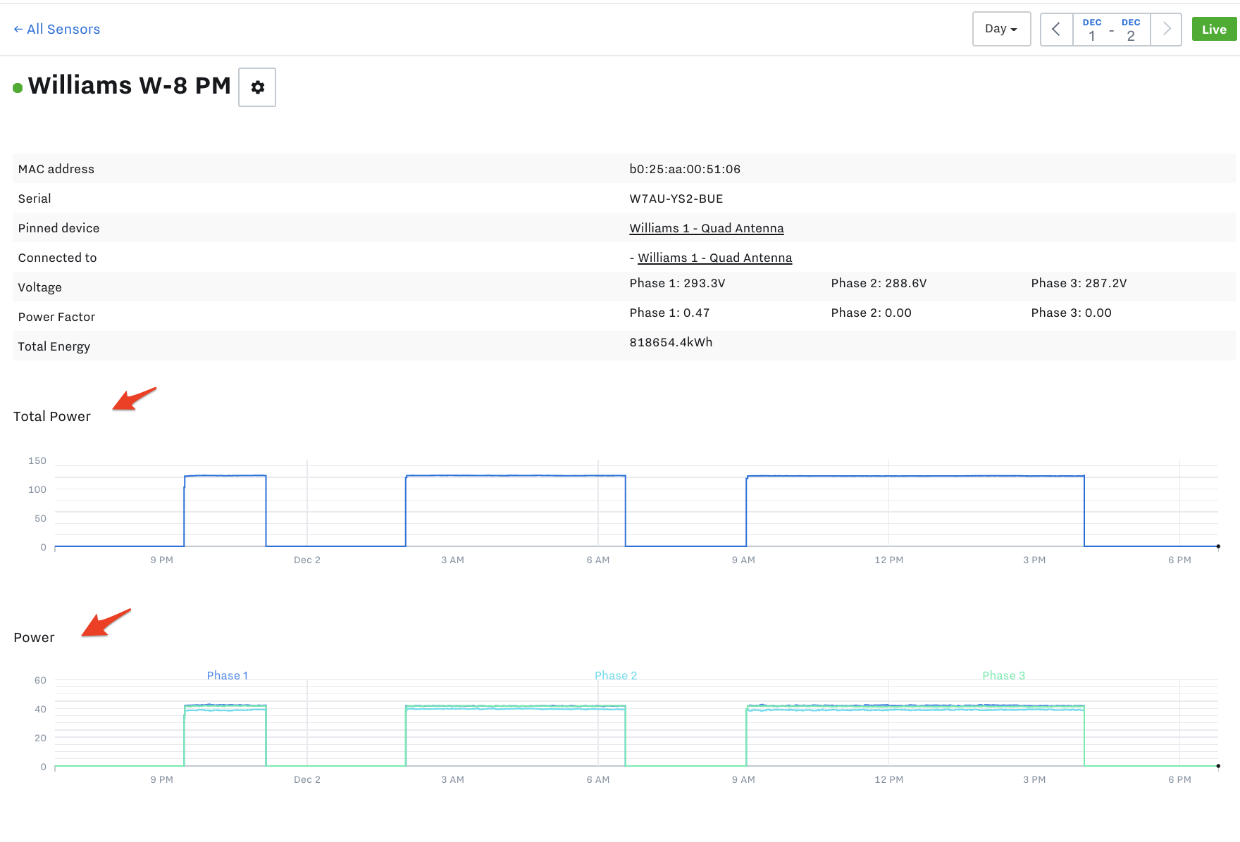
Click on the Name of the Sensor in the Cloud that has the green dot to the left of it
You will be brought to the Sensor details page. Check the readings to ensure it is what you expect:
Confirm phase voltage is correct given your system voltage. Not all possible systems are listed below:
Set up PM20 Power Monitor in the Cloud
Once the physical install is complete, you are ready to configure the device in the Samsara Cloud, which includes setting up: data inputs (for power, voltage, current), dashboards, alerts, and reports.
To learn how to set the Power Monitor up in the Cloud, navigate to our “Set up Devices in the Cloud” Chapter of this User Manual and find the PM20 Power Monitor section.
Appendix
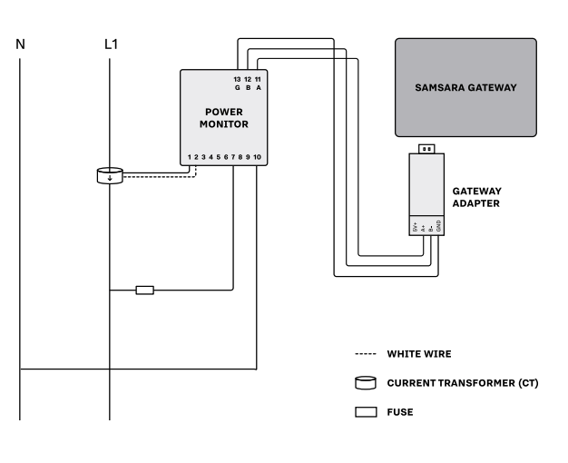
Single-Phase 2-Wire Power Monitoring Wiring for 120V, 240V, 230V
Alternate wiring for Step 3, connecting the power meter.
Connect the CT black wire to port 1 on the power meter and the CT white wire to port 2 on the power meter. Must be completed BEFORE connecting the CT to the hot wire.
Connect the CT so that the L1 hot wire passes through it and the arrow on the CT points towards the load.
Connect the L1 hot line voltage reference wire to port 7 on the power meter.
Connect the neutral line voltage reference wire to port 10 on the power meter.
120V/240V/230V, 2-Wire, Single Phase
Label Line 1 as L1.
Fit CT1 around L1. Make sure the arrow is facing towards the load (in the direction of flow).
Black CT wire connects to Port 1 on the Samsara Power Meter. White CT wire connects to Port 2.
With split core CTs, close the CT around the wire to be measured and press firmly until you feel and hear it click to indicate full closure. The buttons should be fully out. Use a zip tie to ensure the CTs remain securely closed.
To power the meter and get a voltage reference: Use a maximum 1.0 Amp inline fuse on L1. Connect one fuse holder pigtail to the breaker, lug or an appropriate line-tap device, and connect the other pigtail to 16-22 AWG UL rated stranded copper wire for connection to the meter.
L1 connects to Port 7 on the Samsara Power Meter, Neutral to Port 10.
Once the meter is properly mounted to the DIN Rail or enclosure and all wiring is completed, with terminal block covers installed, power can be turned back on.
Meter will then begin cycling through meter values.
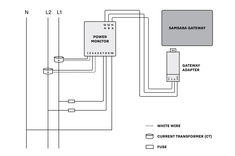
Single-Phase 3-Wire Power Monitoring Wiring for 120/240 volt or 120/208 volt
Alternate wiring for Step 3 (connect power meter).
Wire the 2 CTs to ports 1-4 on the power meter. Connect black wires to ports 1 and 3 and white wires to ports 2 and 4. Must be completed BEFORE connecting CTs to L1 and L2 hot wires.
Connect the CT1 so that the L1 hot wire passes through it and the arrow on the CT points towards the load. Repeat for CT2. Ensure all CTs are oriented with the arrow pointing towards the load.
Connect the L1 and L2 hot line voltage reference wire to port 7 and 8 on the power meter.
Connect the neutral line voltage reference wire to port 10 on the power meter.
120/240V, 120/208V, Single Phase, 3-Wire
Connect the CT1 black wire to port 1 on the power meter and the CT white wire to port 2 on the power monitor. Must be completed BEFORE connecting the CT to the hot wire.
Connect the CT2 black wire to port 3 on the power meter and the CT white wire to port 4 on the power meter. Must be completed BEFORE connecting the CT to the hot wire.
Connect the CTs so that the hot wires pass through it and the arrow on the CT points towards the load.
Connect the L1 hot line voltage reference wire to port 7 on the power meter. The best practice for this is to use a 1A inline fuse and a wire tap.
Connect the L2 hot line voltage reference wire to port 8 on the power meter. The best practice for this is to use a 1A inline fuse and a wire tap.
Connect the neutral line voltage reference wire to port 10 on the power meter.
After all the connections have been securely made, the power can be turned on again. The meter should power on and start cycling through its display.
Single-Phase 3-Wire Power Monitoring Wiring for up to 415 volts (120-415V)
Alternate wiring for Step 3 (connect power meter).
Connect the CT1 black wire to port 1 on the power meter and the CT1 white wire to port 2 on the power meter.
Connect the CT3 black wire to port 5 on the power meter and the CT3 white wire to port 6 on the power meter. Must be completed BEFORE connecting CT to hot wire.
Connect the CT1 so that the L1 hot wire passes through it and the arrow on the CT points towards the load. Connect the CT3 so that the L3 hot wire passes through it and the arrow on the CT points towards the load.
Connect the L1 hot line voltage reference wire to port 7 on the power meter.
Connect the L3 hot line voltage reference wire to port 9 on the power meter.
Install a jumper wire from port 8 to port 10 on the power meter.
Single-Phase 3-Wire Power Monitoring Wiring for up to 415 volts (120-415V)
Label L1, L2 and L3. (Arbitrarily assign labels.)
You will be using 2 CTs for this install. Label them CT1 and CT3.
Fit CT1 around L1. Make sure the arrow is facing towards the load (in the direction of flow).
Fit CT3 around L3.
Black wire from CT1 connects to Port 1 on the Samsara Power Meter. White wire from CT1 connects to Port 2.
Black wire from CT3 connects to Port 5 on the Samsara Power Meter. White wire from CT3 connects to Port 6.
With split core CTs, close the CT around the wire to be measured and press firmly until you feel and hear it click to indicate full closure. The buttons should be fully out. Use a zip tie to ensure the CTs remain securely closed.
To protect the meter, use a maximum 1.0 Amp inline fuse on each line.
To power the meter and get a voltage reference: Tap into L1. Connect one fuse holder pigtail to the breaker, lug or an appropriate line-tap device, and connect the other pigtail to16-22 AWG UL rated stranded copper wire for connection to the meter. This L1 tap connects to Port 7 on the Samsara Power Meter. Tap into L2 and L3 and repeat the connection process. L2 tap connects to Port 8. Be sure to add a jumper to Port 10. L3 tap connects to Port 9.
Once the meter is properly mounted to the DIN Rail or enclosure and all wiring is completed, with terminal block covers installed, power can be turned back on.
Meter will then begin cycling through meter values.
Note: 3-phase, 3-wire, 480v electrical systems cannot be metered with this meter model. For 3-phase, 480v electrical systems, the Samsara Power Meter must have a true neutral in order to meter accurately and avoid being damaged by high voltages.
In cases where there is no neutral on the system being metered, it may be possible to run a neutral from the transformer or electrical panel, to the Samsara Power Meter. Again, this meter must have a true neutral in order to meter 3-phase, 480 volt, electrical systems. This would make it a 3-phase 4-wire system and would also require a 3rd current transformer.