IG41 Install Guide
Summary
This article will provide you an overview of the requirements to successfully install the Samsara IG41 plus IG41 accessories. The IG41 Industrial Gateway is an all-in-one solution to viewing even the most remote environments. Read more about it on our website, blog post, and press release.
IG41 Introduction
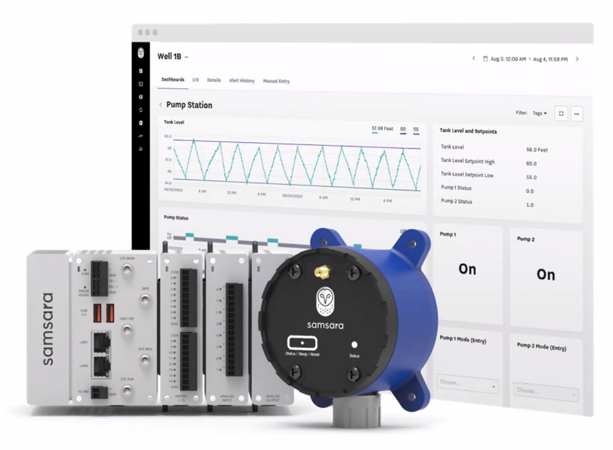
Connect industrial equipment and operations with the IG41, a ruggedized IoT gateway with modular I/O, pre-provisioned cellular, onboard data storage, and dedicated processing for low-latency data transmission to the cloud.
Below includes a photo of the IG41 with the AI and DIO Modules.
IG41 Specs and Accessories
Datasheets and Install Guides
Go to All Datasheets and Install Guides and search for IG41. |
Accessory Options for the IG41
Check out the full list here under “All Samsara Industrial Product SKUs” at the bottom of the article: All Datasheets and Install Guides
Type | Name | Description |
|---|---|---|
IG41 Antennas | Antenna Pack | These are individual “stick” antennas (Wifi, LTE, GPS, LoRaWAN) that work best in areas with good service and when the IG41 is not installed in a metal enclosure. |
Array Antenna | The array antenna is mounted on a flat surface, generally the top of an enclosure. This antenna generally gets a better signal than the “stick” antennas, and forms a watertight seal with the enclosure. | |
Directional Antenna | For areas with the worst service, the directional antenna is recommended. These are typically installed on a 15’-20' push pole, with two coaxial cables with N-type connectors going from the antenna down to the enclosure. Bulkhead fittings can be used to securely pass the cable through the enclosure wall in order to connect to the IG41. This antenna needs to be pointing in the direction of the nearest cell tower, a signal meter can be used to tune the antenna for the strongest signal. | |
IG41 Modules | AI Module | The Analog Input Module can receive 0-10V or 4-20mA signals. There are eight inputs per module. |
DIO Module | The Digital Input Output Module can be configured for digital inputs or outputs. There are two banks of eight points each that can be configured as inputs or outputs. There is one common per bank, all of the inputs or outputs in the bank must be of the same type. It can receive wet or dry contact inputs, and sinking or sourcing. The outputs can be configured as sinking or sourcing as well. | |
IG41 Power Supplies | DIN Rail Power Supply | This is a 24V 5A power supply that can be used with the IG41 and Modules, DIN rail mounted. |
AC Wall Adapter Power Supply | This is a good option for doing bench tests, or where a 110VAC outlet is available. | |
Sensors | HM11 Machine Health Monitor | Real-time monitoring of vibration and temperature. |
EM21 Environmental Monitor | Real-time monitoring of humidity and temperature. | |
EM22 Environmental Monitor (with external temperature probe) | Real-time monitoring of humidity and temperature (with external temperature probe). | |
PM20 Power Monitor | Real-time monitoring of power. | |
CAN Cables | CBL-AG-AOPEN | Powered asset cable harness for power and CAN hi and CAN lo wiring (for engine diagnostics and diagnostic trouble codes). |
CBL-AG-A9PIN | 9 pin cable containing CAN hi and CAN lo wiring (for engine diagnostics and diagnostic trouble codes). This cable allows for interfacing easily with most non-CAT industrial equipment. | |
CBL-AG-ACT9 | 9 pin cable containing CAN hi and CAN lo wiring (for engine diagnostics and diagnostic trouble codes). This cable allows for interfacing easily with most CAT industrial equipment. | |
CBL-AG-ACT14 | 14 pin cable containing CAN hi and CAN lo wiring (for engine diagnostics and diagnostic trouble codes). This cable allows for interfacing easily with most newer CAT industrial equipment. |
IG41 Installation Requirements
Please review the requirements below and verify that your environment meets these requirements for a successful installation.
Tool Requirements
|
|
Safety Requirements
Please adhere to your company’s safety protocols when installing or doing maintenance on the unit
Wear safety glasses
Make sure the site/unit is in an appropriate state for installation
Acquire any work permits needed
Physical Requirements
Gateway dimension
100 mm x 86 mm x 102 mm (no modules included)
Mounting/Paneling
Ensure that there is available space within panel where the IG41 is to be installed
The IG41 should be mounted on DIN Rail, allow at least 25mm on the top and bottom of IG41 for airflow
Antenna
If using the IG inside a metal enclosure, confirm pathway for cabling for an external antenna antenna to be mounted
If connecting to multiple devices on a TCP/IP network via Ethernet an ethernet switch will be needed.
Power Requirements
The IG requires 10-28 VDC. This can be provided by a 24VDC power supply, or the AC Power Adapter (available as an accessory).
Cell Signal Requirements
When installing IG41, please ensure it has sufficient cellular signal at the installation point. Site surveys should be completed with a signal meter to quantify the signal strength at the location. As a general guideline, the gateway does not have issues connecting with the array antenna if the RSSI is stronger than -90dBm. This is not true in all cases as signal quality can affect connectivity as well. For areas with less than -90dBm, directional antennas and potentially signal boosters should be considered.
IG41 Step-by-Step Installation
Physical Installation
All install guides are compiled here: All Datasheets and Install Guides
Notes:
Mount the IG41 to DIN rail in an appropriate place inside a properly rated enclosure
Make sure to allow at least 25mm on the top and bottom of IG41 for airflow
Try to plan the installation to separate high voltage AC wires and 24VDC signal and communications wires to reduce the possibility of electrical noise
Activate the Device
Once you unbox the IG41, find the serial number. The serial number can be found on the backside of the box or on the lower-left corner of the IG41 itself. Go to the Samsara Cloud and activate the device:
Activate Device(s) in the Cloud
Install Antennas
The IG41 can connect with the stick antennas, the array antenna, or a directional antenna. See the Antenna Install Guide for more information about the antennas: IG41 Antenna Install Guides
Electrical Installation
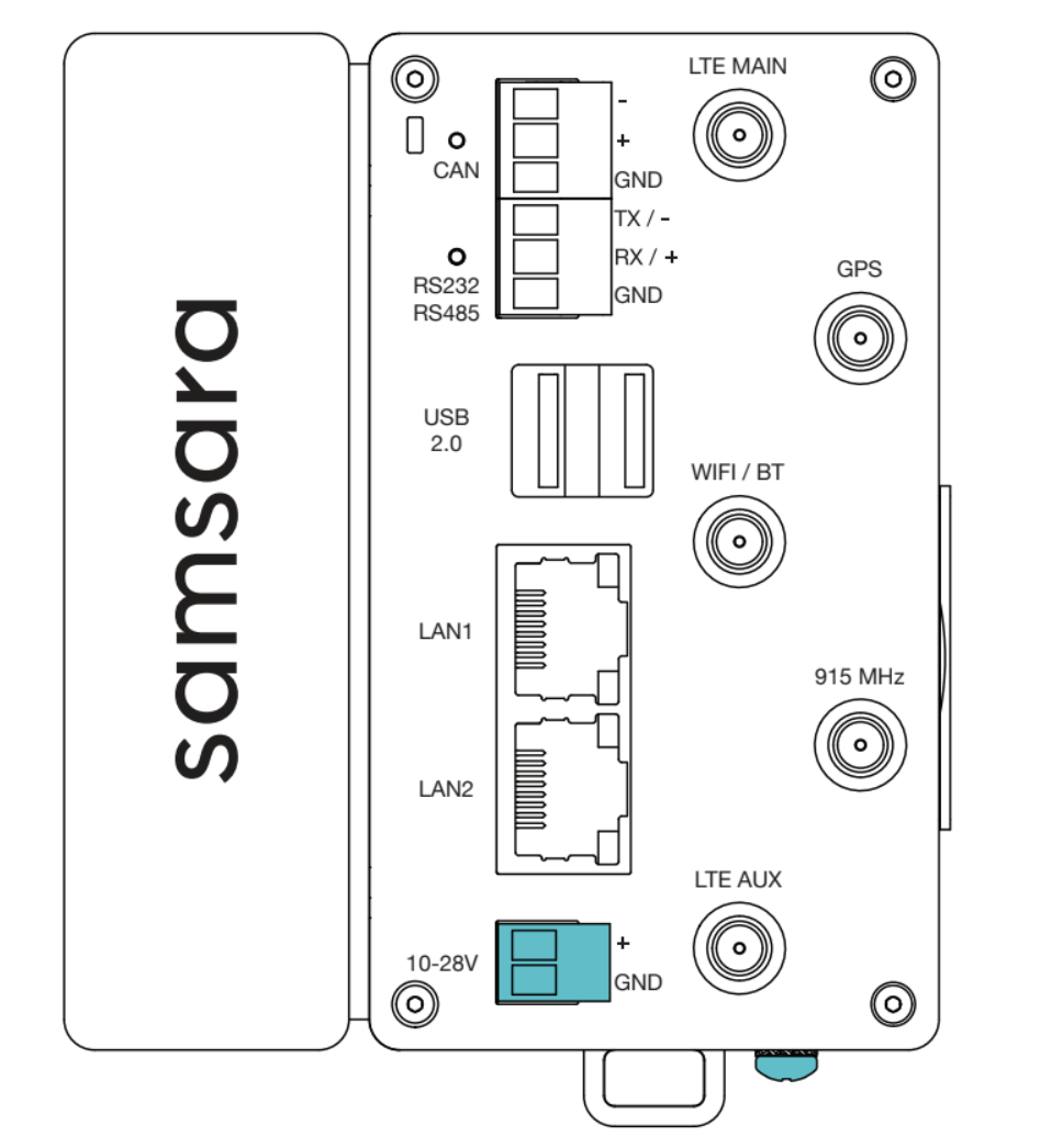
To complete a basic installation, the IG41 needs power and communications to be wired. There are a variety of protocols available. CAN is available with the three pin terminal at the top, and Serial protocols such as Modbus RTU RS232 and RS485 use the three pin terminal just below that. Protocols over ethernet cables, such as Modbus TCP or Ethernet IP, are connected to either on of the RJ45 LAN ports on the front of the device. Configuring these protocols is covered in the IG41 Cloud Configuration linked at the end of this article.
How to Power the IG41
Supply 10-28VDC to the highlighted terminals in the image on the right. This can either be from the DIN Mount Power Supply, the AC Adapter, or another power source within range. The connectors should be removed from the IG41 before screwing wires into the terminals.
When power is applied, the LED will blink white as the unit is booting.
After it has booted, the LED will blink green to indicate that the device is looking for a connection, and will become solid green when it has found a connection.
If the gateway stays in the blinking green state, it is not able to find a connection. Double check the antenna connections and if possible verify the signal strength with a signal meter.
LED Light Guide
For more information on the LED indicator, see this guide: IG41 LED Guide. More troubleshooting steps can be found here: Gateway Troubleshooting .
Note for Installations using Analog or Digital IO Modules:
The gateway may need to update before it will work with the IO modules. If the gateway is powered on for the first time with the modules connected and the main LED turns red, this is the case. Power down the device, remove the modules, and power it on again. Let it stay powered on and connected with a green LED for 30 minutes, then try adding the modules on again after removing power. If this does not work, contact support.
Confirm Connection in the Cloud
After the IG41 has a solid green LED, check the data on the Samsara Cloud by:
Accessing Samsara Cloud with a correct browser - Supported Browsers on Desktop and Mobile
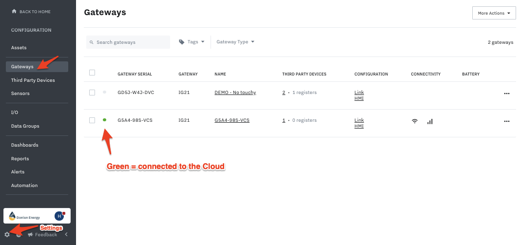
Go to Settings in bottom left of Samsara Cloud, then go to Gateways and make sure the light is Green for the IG41:
Set up the IG41 in the Cloud
Once the physical install is complete, you are ready to configure the device in the Samsara Cloud, which includes setting up: data inputs/outputs, dashboards, alerts, reports, and connecting to 3rd party devices.
To learn how to set the IG41 up in the Cloud, navigate to Set up Devices in the Cloud .