IG15 Install Guide
Summary
This article will provide you an overview of the requirements to successfully install the Samsara IG15 plus IG15 accessories.
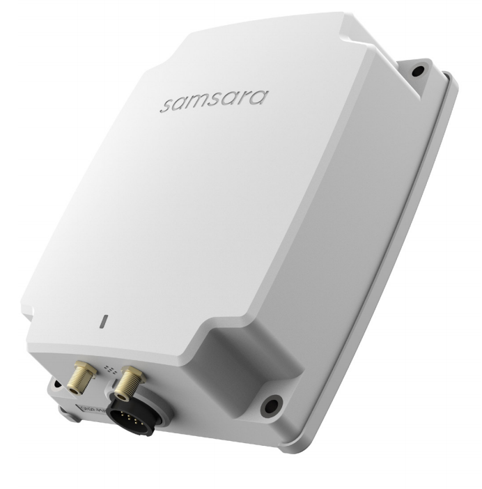
IG15 Introduction
The IG15 Industrial Gateway is ideal for monitoring CAN-based equipment and assets via the J1939 protocol. It provides access to live asset data in customizable industrial dashboards enabling improved operating efficiency, maintenance, and digital service offerings.
It features built-in cellular connectivity with pre-provisioned service, seamless integration with other members of the IG family, and an IP69K-rated enclosure for deployment in the harshest environments.
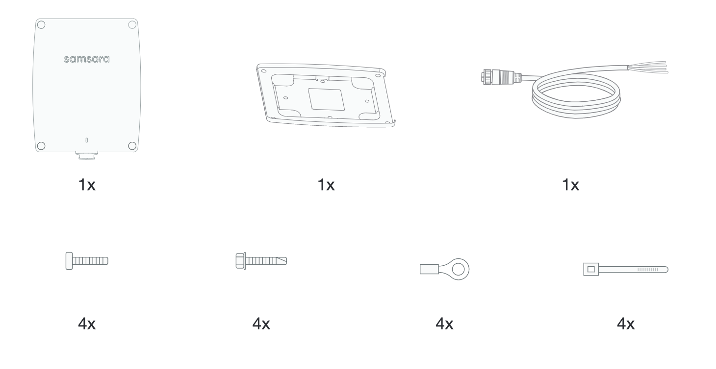
What’s included in the IG15 Box
IG15 Specs and Accessories
Datasheets and Install Guides
Go to All Datasheets and Install Guides and search for IG15. |
|---|
Accessory Options for the IG15
Check out the full list here under “All Samsara Industrial Product SKUs” at the bottom of the article: All Datasheets and Install Guides
Type | Name | Description |
|---|---|---|
IG15 Antennas | Antenna Pack (ACC-IANT-CG) | These are individual “stick” antennas (LTE, passive/unpowered GPS) that work best in areas with good service and when the IG15 is not installed in a metal enclosure. |
Array Antenna (ACC-AANT-CG) | The array antenna is mounted on a flat surface, generally the top of an enclosure. This antenna generally gets a better signal than the “stick” antennas, and forms a watertight seal with the enclosure. | |
IG15 Power Supply | SKU - IG15 BUNDLE | 12-30 VDC capacity. |
Modules (coming soon) | TBD | TBD |
Sensors | Machine Health Monitor | Real-time monitoring of vibration and temperature. |
Environmental Monitor | Real-time monitoring of humidity and temperature. | |
Environmental Monitor (with external temperature probe) | Real-time monitoring of humidity and temperature (with external temperature probe). | |
CAN Cables | CBL-AG-AOPEN | Powered asset cable harness for power and CAN hi and CAN lo wiring (for engine diagnostics and diagnostic trouble codes) |
CBL-AG-A9PIN | 9 pin cable containing CAN hi and CAN lo wiring (for engine diagnostics and diagnostic trouble codes). This cable allows for interfacing easily with most non-CAT industrial equipment. | |
CBL-AG-ACT9 | 9 pin cable containing CAN hi and CAN lo wiring (for engine diagnostics and diagnostic trouble codes). This cable allows for interfacing easily with most CAT industrial equipment. | |
CBL-AG-ACT14 | 14 pin cable containing CAN hi and CAN lo wiring (for engine diagnostics and diagnostic trouble codes). This cable allows for interfacing easily with most newer CAT industrial equipment. |
IG15 Installation Requirements
Please review the requirements below and verify that your environment meets these requirements for a successful installation.
Tool Requirements
|
|
Safety Requirements
Please adhere to your company’s safety protocols when installing or doing maintenance on the unit
Wear safety glasses
Make sure the site/unit is “OFF” and electrical hazards are given consideration for installation
Acquire any work permits needed
Physical Requirements
Gateway dimensions
Mounting/Paneling
Ensure that there is available space within panel (if mounted internally) where the IG15 (Dimensions: 4.1 x 6.0 x 1.9 inches) is to be installed accounting for the cables connecting to the IG (CAN Bus/power cable and cables for external antenna).
Antenna
If using the IG inside a metal enclosure, confirm pathway for cabling for an external antenna antenna to be mounted.
Cell Signal Requirements
When installing the IG15, please ensure it has sufficient cellular signal at the installation point. Site surveys should be completed with a signal meter to quantify the signal strength at the location. As a general guideline, the gateway does not have issues connecting with the array antenna if the RSSI is stronger than -90dBm. This is not true in all cases as signal quality can affect connectivity as well. For areas with less than -90dBm, directional antennas and potentially signal boosters should be considered.
IG15 Step-by-Step Installation
Activate the Device
Once you unbox the IG15, find the serial number. It is located on the box and also on the sticker of the bottom of the IG15. Go to the Samsara Cloud and activate the device:
Activate Device(s) in the Cloud
Power the Device
The IG15 can accept power between 8-36 VDC. In installing the IG15, you will use the power interface from your asset via the open-wire CAN cable or one of the pre-terminated cables supplied by Samsara. When power is not available from the asset, the gateway will run off the internal battery in power-saving mode. While in power-saving mode, the gateway will, by default transmit GPS location data once every 12 hours.
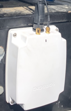
Mount the Device
Using the included alcohol wipe, prep a surface by wiping the area clean of dust and oils for the IG15 to be mounted to.
Attach mounting plate using adhesive and secure with 4 self-tapping screws (bag 1).
Secure the IG15 to mounting plate using 4 machine screws screws (bag 2).

Connect the Cables
If Using Open Ended Cable:
Identify CAN HI and CAN LO on your and connect them to the corresponding labeled wire on the gateway CAN cable. Connect the green wire to CAN LO, and yellow wire to CAN HI. Typically these are green and yellow on your asset as well - if they are not, use the following guide and multimeter to identify the location of CAN HI and CAN LO
The CAN HI wire should be connected to a pin that is registering between 2.5v and 3.5v when using a multimeter.
The CAN LO wire should be connected to a pin that is registering between 1.5v and 2.5v when using a multimeter.
Connect the CAN Cable to Power
Connect the red wire labeled power to a key-switched power source (something that when the key is off, power is not present (Use multimeter to verify)
Connect the black wire labeled ground to the ground (i.e. battery negative terminal).
If Using Samsara-Terminated Cable and Antennas:
Simply plug into intended location (service port). For a permanent installation, it is recommended that the existing service port be unmounted from its location, connected to the Samsara supplied service port, and the duplicated service port be mounted within is
Attach the antenna(s) to the correct ports on the gateway. Go to the IG15 Antenna Guide here: IG15 Antenna Install Guides
Plug the 14-pin connector on the CAN cable into the gateway and twist to secure.
The light on the gateway should turn on. Initially, the light will flash orange indicating that the gateway is searching for a connection. Once connectivity is established, the light will turn solid green (this could take 1-3 minutes)
Allow several minutes for the gateway to download any firmware updates the first time you power it up.
Verify Connectivity
Once the IG15 is powered up, the indicator light should flash orange. In a couple of minutes, the IG15 indicator light should turn solid green. If it does not, ensure that the antenna cables from the array antenna are screwed into the correct ports of the IG15.
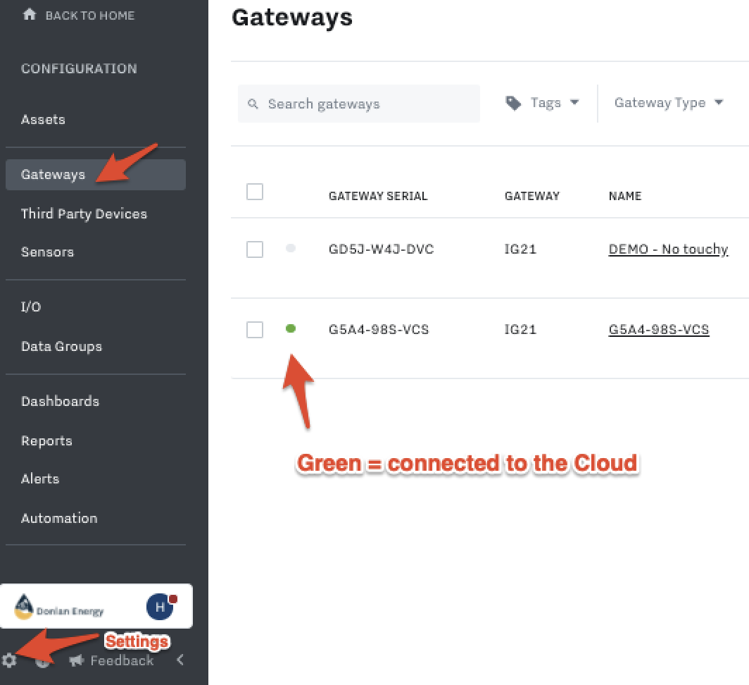
Confirm Connection in the Cloud
After confirming the IG15 is installed (and light is solid green), check the data on the Samsara Cloud by:
Accessing Samsara Cloud with a correct browser - Supported Browsers on Desktop and Mobile
Go to Settings in bottom left of Samsara Cloud, then go to Gateways and make sure the light is Green for the IG15:
Set up the IG15 in the Cloud
Once the physical install is complete, you are ready to configure the device in the Samsara Cloud, which includes setting up: data inputs/outputs, dashboards, alerts, reports, and connecting to 3rd party devices.
To learn how to set the IG up in the Cloud, navigate to Set up Devices in the Cloud .