Set up Modbus TCP in the Cloud
Summary
We will walk through how to set up this type of device in the Samsara Cloud. You will map data inputs according to the protocol the third party device is communicating through.
Set up Gateway
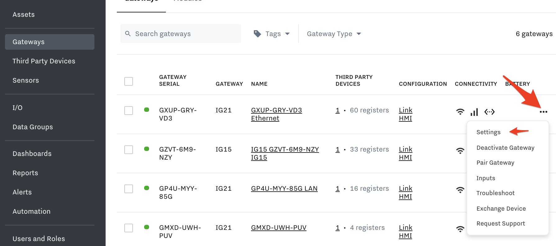
This communication protocol uses an ethernet connection which is established using an IP address. To begin, navigate to the Gateway and select the three dots to the right to go to Gateway Settings:
Fill in the Gateway Device information:
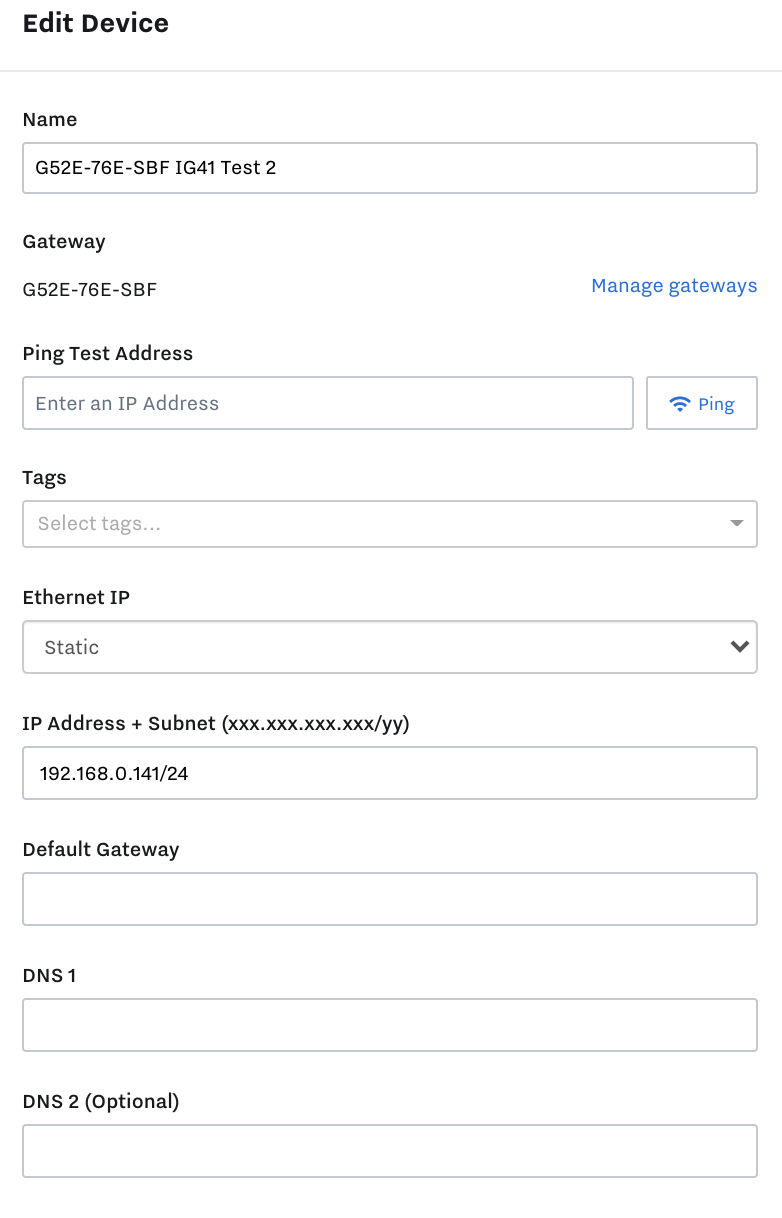
Device Name: This will default to the name of your gateway
Ethernet IP: A dynamic IP will be assigned by a DHCP client, a static IP will be manually selected and remain that IP address until changed. Consult with a network administrator to determine which is right for your network. This example will be for using a static IP.
IP Address + Subnet: Consult with a network administrator to choose an IP address for your gateway which is available on your network. Failure to choose an available IP address can cause network wide problems. The subnet portion of this step refers to the subnet mask, this is based on the number of 1’s in the subnet mask.
255.255.0.0 ---> 16
255.255.255.0 ----> 24
The IP address + subnet seen in the above example is 192.168.127.100/24
Default Gateway: For most applications this field can be left blank.
DNS: For most applications, these fields can be left blank
The gateway is now set up for ethernet connections.
Create Third Party Device
To map your third party registers in the Cloud, first create the device. Go to Settings > Third Party Devices > + Configure New Device. Fill out the details in the box below and hit Create.
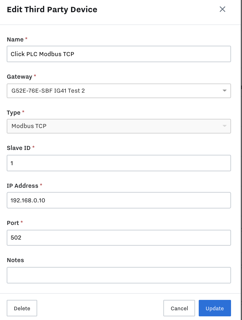
Name: Choose a name for your third party device
Gateway: Select the IG from the previous steps
Type: Select Modbus TCP
Slave ID: For this application, this field can be left unchanged
IP Address: The default IP address of a third party device (i.e MOXA IO Card) can typically be found on the device as seen below. If it is not explicitly specified on the device a quick google search using the device’s model number will be a good place to look. If the IP address of the third party device needs to be changed, consult with a network administrator or refer to the device manual.
Port number: The port number associated with Modbus TCP is typically 502
Create Registers
Add Registers In Bulk
You can use the bulk data setup tool to configure many registers, pins, or tags AND create and map to data inputs or outputs automatically. Read this article for an in depth guide on how to use the bulk data setup tool: Add Registers with the Bulk Edit Tool , or follow along below to see more details on how to configure registers one at a time according to the device type.
Add Registers One at a Time
After specifying the protocol by creating the Device, you now will map the data inputs on the device within your cloud dashboard. These data inputs are called “Registers”.
Within the device, you can set up Modbus registers, and then match sensor inputs coming into the third party device to a Modbus address that Samsara reads from. The register is an agreed upon address where the device sends information to and the Samsara IG pulls information from.
Some devices, such as Modbus-enabled sensors, have preconfigured registers mapped out to specific values. Consult the device manual for this list. PLCs and flow computers have Modbus register maps that must be configured by the user, placing the desired value into an address that can be read by the Samsara IG.
To start, go to Settings > 3rd Party Devices > select the 3rd party device you would like to map > + Configure New Register
Once selecting +Configure New Register you will see the screen below

Name: Give a name most appropriate for the data input (your choice).
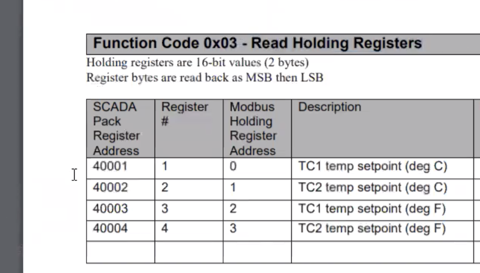
Function Codes: The function code used explicitly depends on the Modbus address being read and should be specified in the third party device’s user manual. For example, Modbus addresses in the 4x range (40001, 400001) require function code 3 to read.
1 - Read Coils - Digital Input
2 - Read Discrete Inputs - Digital Input
3 - Read Holding Registers - Analog Input
4 - Read Input Registers - Analog Input
5 - Write Single Coil - Digital Output
6 - Write Single Register - Analog Output
Address: This refers to the location of the bit we are extracting (multiple bit scenarios will be handled next in the length field). For Samsara, addresses always begin at 0, therefore an offset may be required depending on the device’s own addressing. If an address isn’t reading data, try subtracting 1 from it on Samsara’s side.
Example: The first input (DI0) on a discrete input card would be function code 2 and address location 0000
Example: The 4th input (AI3) on an input register would be function code 4 and address location 0003
Length: This refers to the number of inputs this register will use. The Address refers to the location of the first bit in the register, the length determines how many addresses are included.
Example: The first input (DI0) on a discrete input card would be 0000, with a length of 3 this register will consist of addresses 0000, 0001, and 0002.
The registers you require will be explicitly listed in your third party device’s Modbus manual. For example, you can see the image below off the SCADAPack Manual.
Scale Factor: You can use this to scale up or down the data input (e.g. to make the value 10X larger, enter “10”. To make the value 1/10th, enter “0.1”). If you do not want to scale the data, simply leave this field as a 1
Data Type: Data type corresponds to the length of the value you want to use to view your data. For example, an Uint16 would be an unsigned integer which is a whole number, so would not be broken down into decimal places, and the 16 corresponds to 16 bits of data, which means that the highest value the number can be is 2^ + or - 16. Choose your data type according to the best format to display your data. If you would like your data to have a decimal places, select a float data type. Ensure that you are receiving data in the same format it is output.
Byte Swap and Word Swap: This is an option to change the format in which Samsara interprets the data, e.g. 1,2,3,4. You have 4 bytes of data, and each byte could mean 8 bits. If the third party device sends the data out in standard byte order, e.g. 1,2,3,4, another device could interpret that in their own format, e.g. 2,1,4,3. This would be an example of byte swapping, because each byte in a word is being swapped.