IG41 - Communication Protocols and Wiring Diagrams
Summary
We will walk through the supported comms protocols and the wiring diagram for each on the IG41.
IG41 Supported Communication Protocols
This section provides an overview on how to physically connect with various third party devices. The IG41 can communicate with third party devices from other manufacturers via Modbus RTU, Modbus TCP, Modbus ASCII, Ethernet IP, CANBUS, MQTT, and OPC-UA. This enables the IG and Samsara cloud platform to be able to read and write data from other PLCs, machines, and sensors.
Note: Only Modicon Modbus is supported, not Daniels/Enron.
Further information on Cloud configuration and setting up third party devices within the Samsara Cloud is covered in a future Chapter: Set up Third Party Devices
Supported Serial Communication Protocols
IG41 supports multiple protocols via 3-wire serial communication via its built-in serial adapter, with the choice of RS232 or RS485.
RS232 Wiring Diagram
RS232 supports connection to only a single device, so the wiring is relatively simple.

RS232 is designed for connecting 2 devices over short cable runs. No termination resistors or biasing resistors are required. For connecting to multiple devices or over long cable runs, RS485 should be utilized.
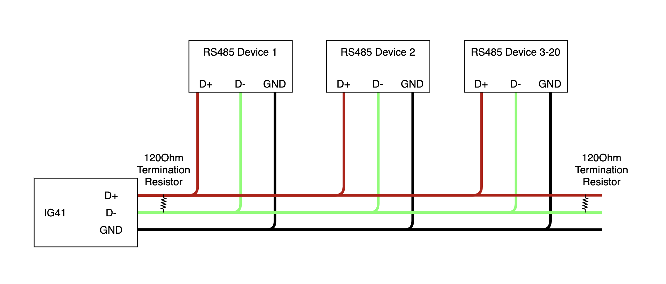
RS485 Wiring Diagram
The diagram below shows how to properly wire the IG41 to a third party device over a RS485 connection. Termination resistors may not be required for very short runs, but are generally recommended for improved reliability. Pull-up and pull-down resistors may also be needed in environments with significant RF noise.
Supported serial protocols: Modbus RTU, Modbus ASCII, Interactive Serial, and ROC Protocol.
Modbus RTU / Modbus ASCII
The IG41 can be be used as a Modbus client to read data from Modbus servers.
At this time, the IG41 CANNOT act as a Modbus server.
Supported function codes:
Function Code | Description |
|---|---|
Function Code 1 | Read Coils |
Function Code 2 | Read Discrete Inputs |
Function Code 3 | Read Holding Registers |
Function Code 4 | Read Input Registers |
Function Code 5 | Write Single Coil |
Function Code 6 | Write Single Register |
Function Code 16 | Write Multiple Registers |
Configure Device
Modbus RTU and ASCII protocols are supported over RS232 and RS485. Configuration options must be set correctly based on the configuration of the connected Modbus server(s).
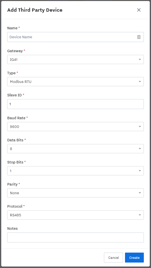
When add a new 3rd Party Device using Modbus RTU or ASCII all configuration fields are required, with the exception of the Notes free text field. For maximum reliability and compatibility we recommend using a Baud Rate of 9600, 8 Data Bits, No parity and 1 Stop Bit.
Modbus TCP / Modbus RTU over TCP
The IG41 can also be used as a Modbus client to read data from Modbus servers connected via Ethernet networks.
At this time, the IG41 CANNOT act as a Modbus server.
Modbus TCP and Modbus RTU over TCP protocols are supported over ethernet connected networks. Configuration options must be set correctly based on the configuration of the connected Modbus server(s).
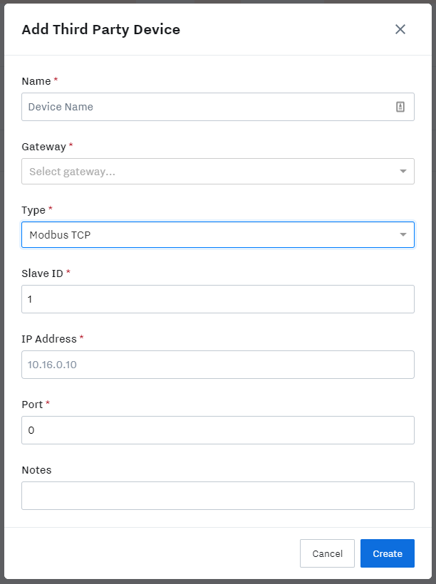
When add a new 3rd Party Device using Modbus TCP or RTU over TCP all configuration fields are required, with the exception of the Notes free text field. The default port for most Modbus TCP servers is port 502. Some Modbus TCP servers do not require a Slave ID to be configured, in which case it can be left as ‘1' or '255’.
NOTE: The IG41 must have a valid IP address configured on at least one of its interfaces, and must be able to communicate with the IP address of the Modbus server that is being configured. You can use the ‘Ping’ command to test connectivity - see this article for more information: Troubleshoot Third Party Devices
ROC Protocol
The IG41 supports a subset of the Emerson ROC Protocol in order to communicate with the Emerson Floboss range of flow computers. The IG41 is able to read and write TLPs from a connected Floboss and to read and set the current time of the unit. See Emerson documentation for more information on the ROC protocol.
The IG41 supports the ROC protocol over TCP connections as well as RS232 and RS485 serial connections.
For maximum throughput and reliability we recommend using the ROC protocol over TCP via an ethernet port.
ROC Serial Wiring Instructions
If you are using RS232, connect to the IG41 to an RS232 capable port on the controller
For Floboss devices, this may be the LOI port
If you are using RS485, connect the IG41 to an RS485 capable port on the controller
If you are unsure about port capabilities, please refer to the device-specific manual.
ROC communication ports must be configured correctly via the ROCLink800 software package, available from Emerson.
Configuring the 3rd Party Device
When adding a ROC protocol 3rd Party Device, you must specify the connected ROC device’s Controller Unit and Group IDs, as well as specifying a Host Unit and Group ID for the IG41 to use. If the connected ROC device’s ID and Group are not known it is possible to use ID 240 and Group 240 for testing purposes - however all connected ROC devices will respond, which may not be desirable.
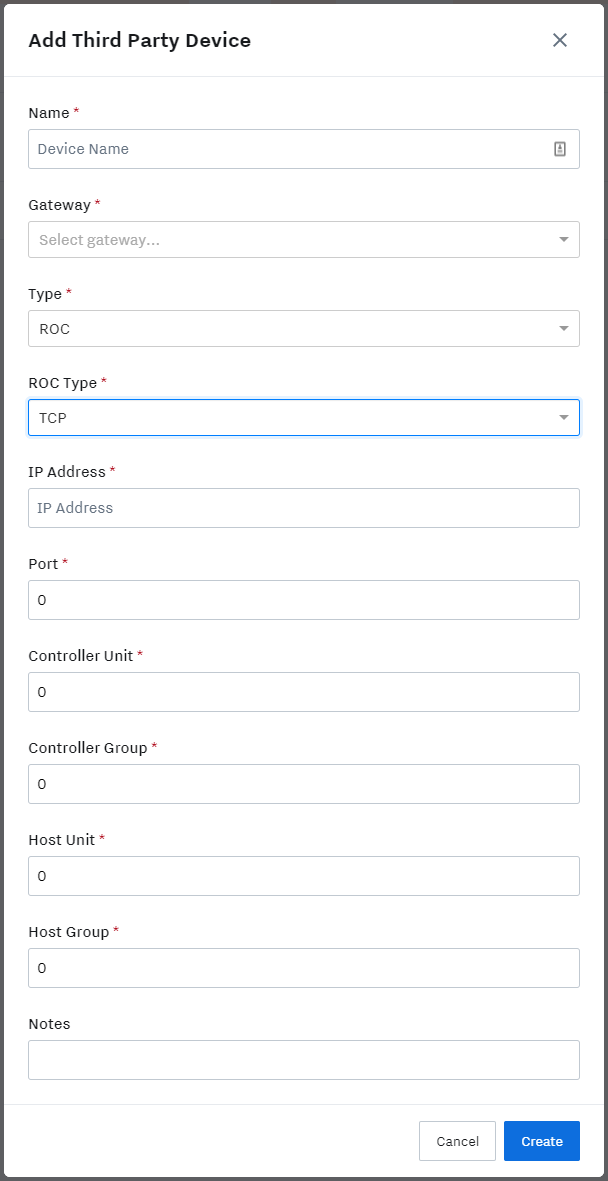
For TCP connected devices, the ROC device’s IP address and port number must be supplied. The default port number is 4000.
For serial connected devices, the serial protocol type must be supplied (RS-232 or RS-485) as well as baud rate, data and stop bits and parity type.
Currently Supported ROC OpCodes
Currently the Samsara ROC support includes:
OpCode | Description |
|---|---|
OpCode 180 | Read one or multiple parameters in a single request |
OpCode 181 | Write one or multiple parameter in a single request |
OpCode 7 | Read ROC device real-time clock (returns Unix epoch time in milliseconds) |
OpCode 8 | Set ROC device real-time clock (takes Unix epoch time in milliseconds) |
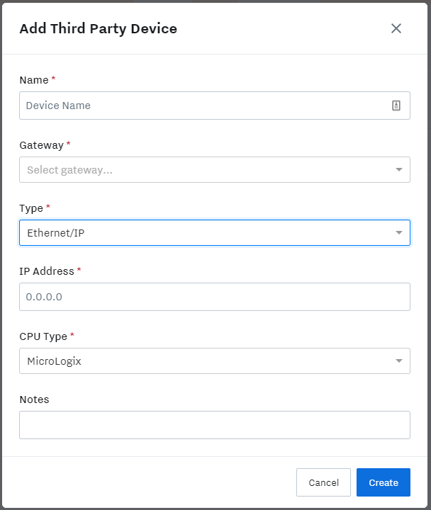
EtherNet/IP
IG41 supports a subset of the EtherNet/IP standard for connecting to a range of Allen-Bradley PLC devices. Generic EtherNet/IP is not available at this time. IG41 is able to read and write specific Tags from Allen-Bradley devices. Both read and write are supported.
The current list of supported A-B PLC families:
|
|
The IP address of the connected device, along with the A-B PLC type must be provided when configuring a new EtherNet/IP 3rd Party Device.
Ethernet/IP Wiring Diagram
EtherNet/IP devices should be connected over Ethernet directly or via an Ethernet switch. Connect one end of the the Ethernet cord into the IG41 via the LAN1 or LAN2 port (the one that you set a static IP to). Connect the other end of the Ethernet cord into the Ethernet Switch or Ethernet directly.

NOTE: As with other Ethernet connected devices, the IG41 must have a valid IP address for the connected network. The two ethernet ports share an IP address. Connectivity from the IG41 to the EtherNet/IP device can be checked with the ‘Ping’ tool - see this article for more information: Troubleshoot Third Party Devices
OPC UA
IG41 supports reading data from an OPC UA protocol server.
Currently, IG41 cannot serve data via OPC UA.
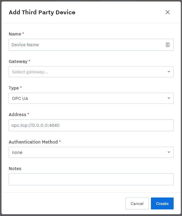
OPC server IP address and port information must be provided.
NOTE: At this time OPC servers requiring authentication are not supported.
MQTT
Support for subscribing to, and publishing to MQTT Topics via an MQTT broker is coming soon.
CAN Bus
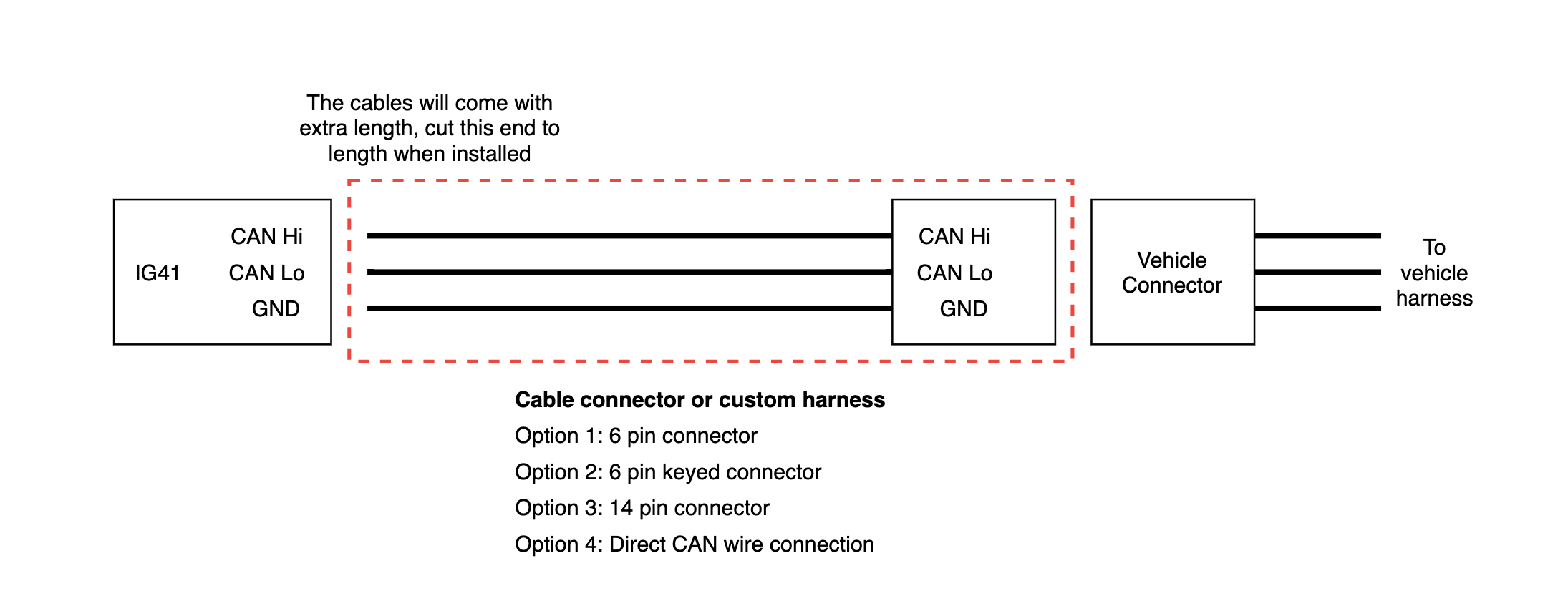
The IG41 can connect to J1939 CANBUS networks to read sensor values and diagnostic information. The IG41 has a three wire terminal to connect to CAN networks, which can use a variety of different connectors depending on the equipment. Samsara can recommend which CAN (J1939) cables should be used based on the equipment.
If a service port is going to be used to connect the IG41 to the CANBUS:
Identify which port type is on the equipment.
Reach out to Samsara to recommend which CAN (J1939) cables should be used based on the equipment with a photo of the service connector.
Please note: the end of the cable will need to be slightly modified for installation into the IG41. Simply cut the cable to length and strip the appropriate wires (as shown in the below diagrams) and terminate into the IG41.
Spec the Wires
If a direct connection into the CAN Bus wires or a custom harness is going to be used (ie, behind a service port / butt-splicing into existing harness), it is recommended to use cables designed to meet the required environmental conditions for the application. Typically, simple shielded twisted pair will work for most applications. A great supplier of cables and connectors is WayTek Wire.
Can Bus Wiring Diagram
The diagram below shows a general CANBUS connection for the several different connection options.
CANBUS Cloud Setup
Now that the physical installation is finished, it’s time to set up the cloud. View the following article for more information: Set up CAN Bus in the Cloud