Set up ROC Device in the Cloud
Summary
We will go through the steps to set up a ROC device in the Cloud once it’s physically installed.
Step 1: Configure ROC Parameters
ROC Parameters need to be located in ROCLINK Software or extracted
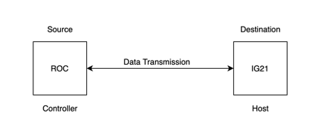
Controller Unit ID = Source = ROC ID (Example: 172)
Controller Group ID = Source = ROC GROUP (Example: 2)
NOTE: If you cannot determine the correct controller details, you may set Controller ID to 240 and Group ID to 240 if you are directly connected to a single ROC device. Any device connected will respond when these IDs are used. Once the correct details are obtained be sure to update the 3rd Party Device settings.
Host Unit ID and Group ID are the parameters used by the IG itself and can be any number 1-240 defined by user. These should not be the same as any other ROC devices connected to the IG.
HOST Unit ID = Destination = IG21 ID (Example: 3)
HOST GROUP ID = Destination = IG21 ID (Example: 1)
Finding the ROC Controller ID and Group ID
If you have ROCLINK 800 software, please follow these steps to find device parameters:
Connect ROC device to PC using ROCLINK Software (Direct Connect)
Navigate to System > Opcode Table > #1
Navigate to Point Type = System Variables > Logical Number = SYS 1
Make sure the “Show Current Value” box is checked
Select “0 – Device Address” and note the current value as the Device ID
Select “1 – Device Group” and note the current value as the Device Group
If you do not have ROCLINK software, please follow these steps:
Confirm ROC device LOI port is wired to the IG21
Set Device Address to 240
Set Device Group to 240
Add TLP 15,0,0 – This will report the Device Address
Add TLP 15,0,1 – This will report the Device Group
Update Device Address, and Device Group to reported values
Step 2: Add the Device in the Cloud
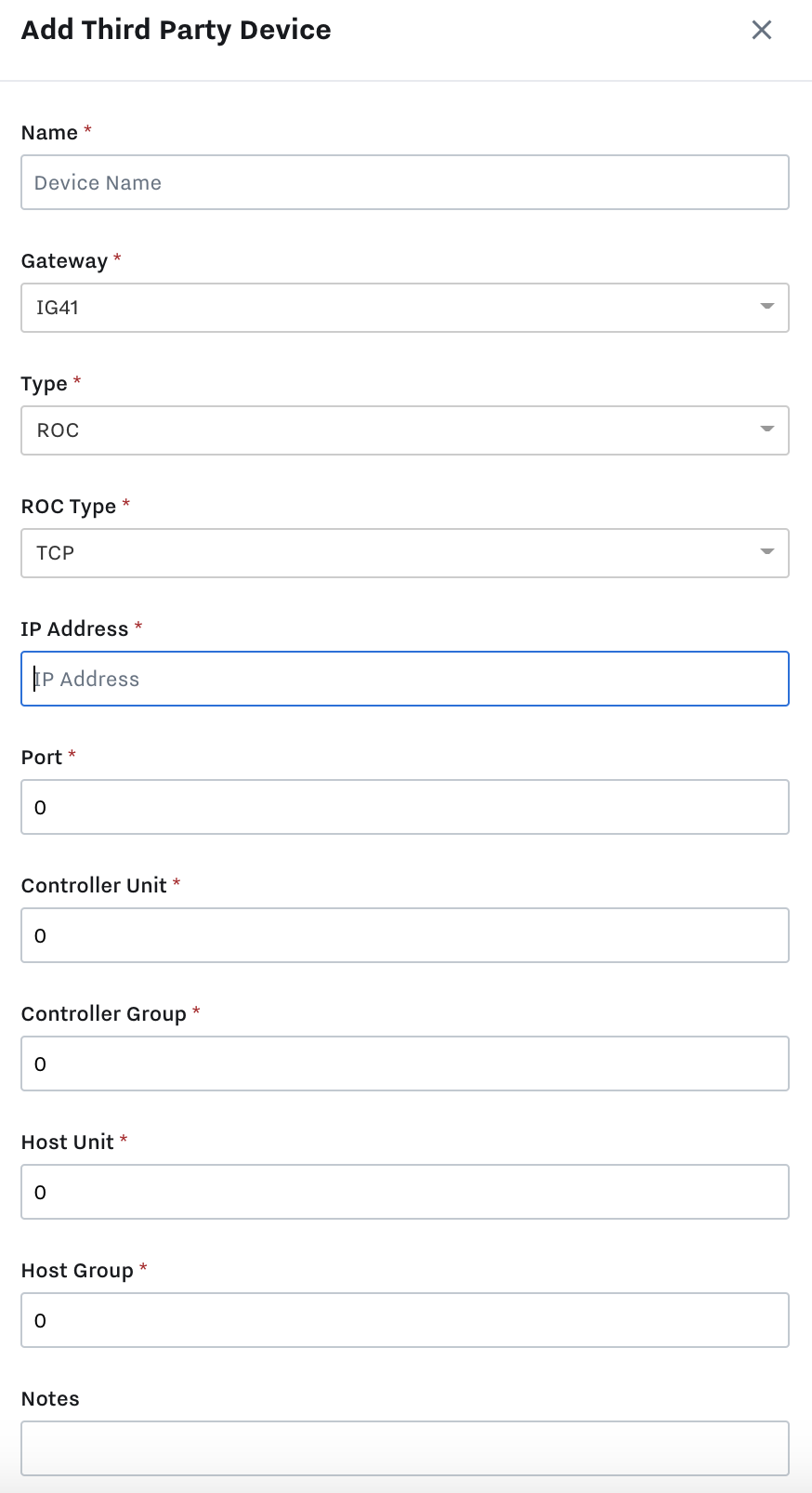
In the Samsara Cloud, navigate to 3rd Party Devices and select “Add New Device”
Fill in the required fields (Use Step 1 to fill in Controller and Host information)
Create Device
Step 3: Create TLPs
(NOTE: TLP = point Type, Logical Number, Parameter, this is the name given to datapoints within the ROC device)
Create a new register in the 3rd party device
Remember TLP, these are found in the OpCode Table in the ROCLINK800 Software
Fill in required fields to create registers (12,0,0 is the internal clock’s seconds counter)
Create accompanying Data inputs so we can monitor the register values
Troubleshooting
Data Inputs are reporting “0.0” – if data is reporting 0 then we likely missed a parameter. Everything must be correctly correlated for connection to work. Go back and double-check these items:
Controller ID, Controller Group – Set these to 240 and 240 temporarily and see if data starts streaming
Rx,Tx pins – try swapping these wires
Confirm in ROCLINK Software that ports are enabled and available – COMM2 port is optional in many devices which is why this manual uses the LOI port
My data is streaming but it is wrong – if data is wrong, it is likely that the data type is incorrect. Use these steps to confirm data type:
Navigate to OpCode table in ROCLINK Software
Select the TLP of choice
Confirm the reported data type is what you have in the register