Remote Connection via VPN Tunneling
Summary
If you need to remotely connect to an existing PLC for programming purposes, you can use VPN tunneling. We go through how to do this in this article.
VPN Tunneling Overview
Please note, this is a temporary tunnel and should not be used for indefinite periods.
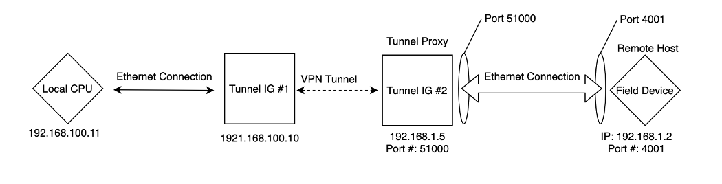
VPN Tunneling will give you the ability to temporarily access a field device remotely using two industrial gateways (IGs). The first IG, Tunnel IG #1, will be connected to your local device, such as a computer, and the second IG, Tunnel IG #2, should be connected to the field device.
Connect the first IG to the computer, or other local device, using an ethernet cable. Ensure both devices are on the same subnet. The laptop should be able to successfully ping the IG and vice versa.
Connect the second IG to the field device. Ensure both devices are on the same subnet. If possible, ping the IG from the end device or ping both devices from a computer on the network to ensure communications are active.
Within the cloud dashboard, navigate to Settings > Gateways > select the three dots next to the Tunnel IG #1> Inputs > Tunneling > click the Add button
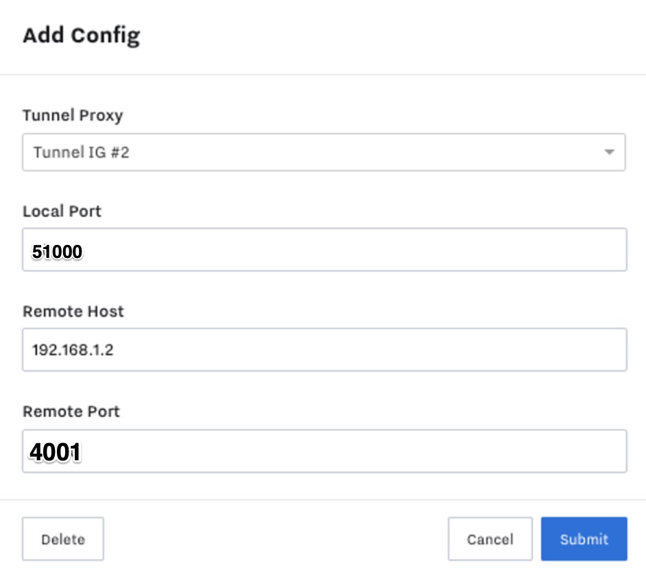
Gather port information that you will use in the next step.
Note
It is important to mention that the available ports to use when selecting a local port are:
102
9999
11740
44818
49999
50000-51000
All other ports on the IG are blocked for other use. The remote port is typically specified in the field device’s software or manual.
NOTE: Port 4001 is used by Tunnel IG #2 to access the field device, Port 51000 is then used by the field device to communicate back to Tunnel IG #1. These ports can be thought of as doors -- Port 51000 should open and close doors that allowTunnel IG #2 to communicate with the device through Port 4001.
Example inputs for configuring a VPN tunnel: Local Port should be the 50000-51000, 9999 range. Remote Port should be the actual port number
The VPN connection should now be open. In the software you are using to access this field device, use the IP address of Tunnel IG #1 (192.168.100.10 or 192.168.100.10:51000 for webservers) and you will tunnel into the field device (at 192.168.1.2).
Note: See Below for additional information on connecting to specific devices and troubleshooting. Some devices may require additional steps for a VPN tunnel to be successful.
Connecting to a ROC Device
If you’re unsure of what port the remote device communicates over, the program Wireshark can be used to discover the correct port. Go to the troubleshooting guide at the end of the article to follow those steps.
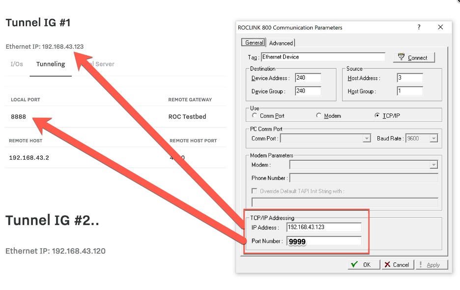
Once configured, the tunneling configurations should look like this:
Next, you’ll need to make a connection. Open ROC software on your laptop. Configure the Ethernet connection:
The IP Address is set to the IP for Tunnel IG #1 (the local IG)
The Port Number is set to the local port as configured in the step above (8888)
Lastly, double click the ROC Ethernet Device to attempt a connection. You should see the following if the connection is successful. If not, go back to the beginning steps and make sure everything is configured properly.
MicroLogix 1100 Differences
Ports
Allen Bradley has a fixed port for it’s controllers. Most likely the port will be 44818. This needs to be set for the Local and Remote Port in the IG Tunnel setting.
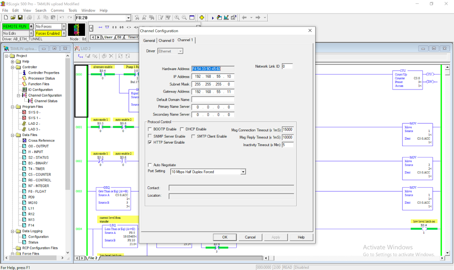
Allen Bradley PLC Default Gateway
The PLC settings will need to be changed to accommodate a default gateway. If using RSLogix 500, double click Channel Configuration and move to the ethernet driver tab. Set the Gateway Address to the address of the Remote IG21 used for tunneling (Tunnel IG #2).
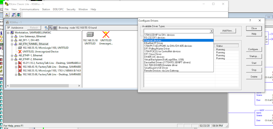
RSLinx
The Allen Bradley driver must be changed when connecting remotely. Create a new driver in RSLinx of the type “Ethernet Devices” (Typically EtherNet/IP is used with a local connection).
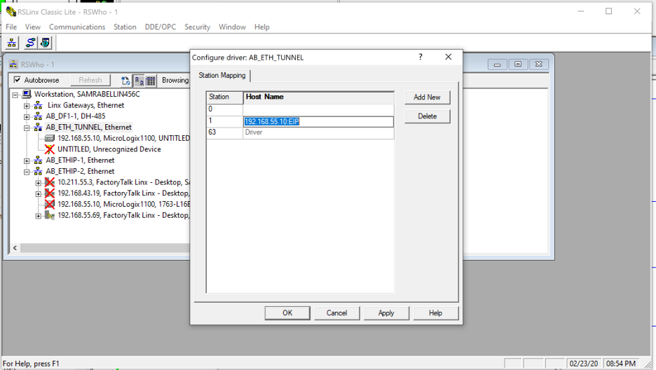
After it is created, right click to configure it and add the IP address of the PLC. Add the suffix “:EIP” for MicroLogix controller so the driver knows to look only for the 44818 port. If this is successful, the controller icon next to the IP address will not have a red “X” over it. It should be possible to connect normally now.
Troubleshooting
Device failing to respond
If you are noticing that the software is reaching the device but it is not able to respond you may be experiencing issues related to the remote port. The remote port is what allows the field device to communicate back to your computer through the VPN tunnel. Confirm you are using port 9999 or a port between 50000 and 51000. Additionally, try rebooting the gateway to restart services.
Using Wireshark to find the communication port your device uses
If you want to remote tunnel into a device, but are unsure of what port that device communicates over, the program Wireshark can be used to discover the correct port. In order to accomplish this, you will need to connect directly to the device first (e.g. laptop to device) before we can begin setting up the VPN Tunneling settings.
Connect your computer directly to the device you’d like to use for VPN Tunneling via ethernet (this is the easiest method as it will reduce the amount of network noise and make it easier to find the network data packets we’re looking for).
Download and run Wireshark.
Under the “Capture” section, select your ethernet device. If you are unsure of the name of your network interface (the ethernet port), you can try one of two things:
For Windows
Attempt a connection with your device in order to generate some network activity. This will create a noisy line graph next to the network interface that corresponds to the ethernet port.
In Windows, open the “Network and Sharing Center” to find your active network connections. You can open it directly by entering this into the start menu search: control.exe /name Microsoft.NetworkAndSharingCenter
For macOS
Open the Spotlight Search (command + spacebar) and open “Network Utility”
To begin capturing data double click your network interface, in this example it is “Dongle Ethernet Port”. It may immediately start displaying network data, we can ignore this data for the time being.
Now we’re ready to launch the necessary software to connect to our device. In this example, we’ll be using PCCU32 to connect to a TotalFlow device. This is a great example as the software does not allow you to change the port number it uses to communicate to the TotalFlow. As each device is different, you’ll need to configure your software to work with your device (find the correct IP Address, communication method, etc).
Once everything is configured, it’s time to attempt a connection with the device. In this example, the laptop and the Totalflow have the following IP addresses. This is important to know when we look at the data flowing into Wireshark.
As soon as you are connected, click the “Stop Capturing Packets” button in Wireshark to prevent it from collecting additional data (and scrolling past the data you want to see).
The information we want is most likely in the first TCP packet that appears between the laptop’s IP address (source) and the TotalFlows IP address (destination), as seen in the above screenshot.
The port can be found under the “Info” column, and will be the second number after the arrow that points right. In this instance, we are looking for port 9999.
Now that we have the port number used to connect to the remote device, we can begin setting up the VPN Tunnel.