IG61 Hardware Install Guide
Samsara IG61 Introduction
The Samsara industrial IoT platform combines hardware, software, and cloud to bring real-time visibility, analytics, and control to your operations.
The IG61 is a robust industrial gateway with built-in cellular, expandable IO, high-capacity onboard storage, and an advanced processor that connects and controls sensors, existing PLCs, controllers, and on-site servers.
The IG61 offers both cloud connectivity for scalability and edge processing for low-latency automated control, with the ability to connect assets via common industrial protocols and expandable digital and analog IO.
Assemble the IG61
You can find the full IG61 data sheet here.
After unboxing the IG61, you may need to assemble additional expansion modules depending on your use case and what you purchased.
You may have an initial backplane, expansion backplane, IO card(s) - analog input/analog output/digital, and/or an additional 24V power supply. Assembly must be completed before the IG61 is powered on to avoid any potential hardware damage.
First, orient the IG61 so the barcode in the corner is facing you and the Samsara logo is upside down.

On the device there will be a panel with 2 screws. Remove the screws and plate to expose the backplane connector port.

Install the shield (plate with big yellow caution sticker) using the 4 black screws included with the backplane.

Connect the backplane to the IG61 by sliding the connector through the opening in the shield. Secure in place using the silver screws included with the backplane. The unit may not work without the screws installed. Ensure that the backplane clips on either side are pushed down into the IG61.


The clear tab located on the IO card will provide more information about configuration such dip switch orientation for specifying voltage or current input. Review this before installing card to ensure card is correctly configured.

Align sliders on top and bottom edges of IO card with IG61 then gently slide the IO card(s) into place on the backplane. Push down clips into place for each card. These clips ground the card to the IG61, the card will not work if these are not firmly clipped into place.


The module number is configured using the red dial on the face of the IO card. The initial position of 0 in the first card, and 1 in the second card, can be seen below. The bubble is always on the left of side of the selected module number.

Your IG61 is now fully assembled and ready to be powered up.
Expansion Backplane Only
If you ordered an expansion backplane, slide it into the first backplane and push clips down. Slide additional IO card(s) into place and push clips down. Insert a blank card if needed. For output cards, an additional power source may be required.


Power the IG61
You can use the 24V power source to supply the IG61 with power. If a 24V source is already available in a panel then you may use that instead.
Unbox the 24V power source and connect the cable with the green, white, and black wire to the AC side of the power source. Do not plug the cable in to a live power source until instructed. Make sure wiring is completely verified before turning on. The color code is:
Green | Ground (⏚) |
White | Neutral (N) |
Black | Power (L) |
Locate the power block (connector) that came with the IG61. It may already be inserted into the left side of the IG61. This will be used to connect the power source to the IG61. Using 2 wires, connect the + from the DC side of the power source to the first port on the power block (V1+) then connect the - to the second power on the power block (V1-).
Now insert the power block into the IG61 and confirm the screws on the power block are tight and the wires will not slip out.


Note: Redundant power supply can be installed using V2+ and V2-
Wire the IG61
Physical Wiring
The terminal blocks on the IG61 differ from the IG21 screw terminals. These terminals are spring loaded and operated by pushing a small flat head screwdriver into the block to open the gate.
There will be two windows on the face of the terminal, one for the wire and their other for a small screwdriver. When the screw driver is gently pushed into the block, a small door will open and allow a wire to be inserted.
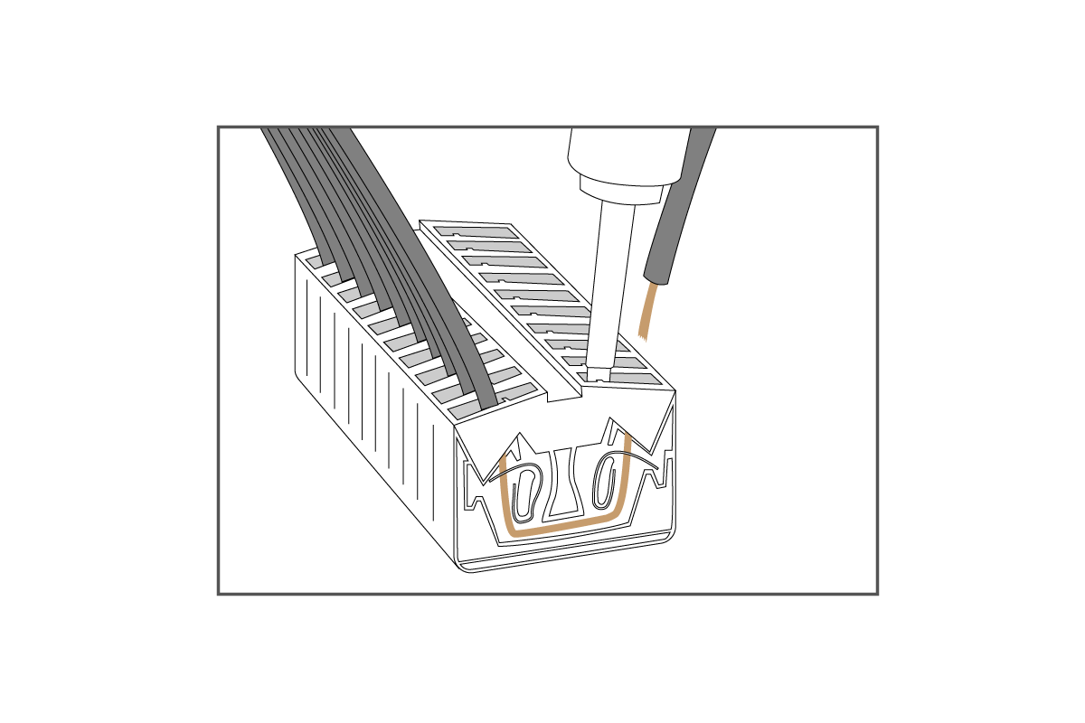
Make sure the IG61 is safely installed or placed on a sturdy platform because this will take two hands to do correctly. Have the wire of choice in one hand, and your screwdriver in the other. Insert the screwdriver to open the gate and maintain pressure to hold the gate open. While the gate is open, insert the wire into the gate. Once the wire is placed into the gate, pull the screwdriver out and the gate will close on the wire, securing the connection.
It is good practice to gently tug on the wire to ensure the gate has a solid hold on the wire. This will avoid future connectivity issues and ensure that if someone hits a wire it will not fall out easily.
To remove the wire, follow the same steps as above. Simply ripping the wire out can damage the terminal or cause it to become blocked if part of a wire remains lodged in it.
Digital Inputs
The digital inputs on the IG61 can be configured as sinking or sourcing type. Power must be supplied by an external source in both configurations. It is good practice to use a common power source (24V) and ground (GND) for all connections.
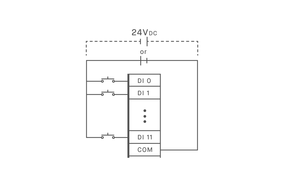
Sinking Input Configuration
Insert the GND wire into the COM Port.
Supply 24V to the opposite side of the contact
When the card senses 24V it will be considered ON.
Sourcing Input Configuration
Insert 24V into the COM Port
Supply GND to the opposite side of the contact
When the port senses GND it will be considered ON
Digital Outputs
The digital outputs on the IG61 are of the sinking type. This means our card does NOT supply power to a contact. The power must be provided from an external source.
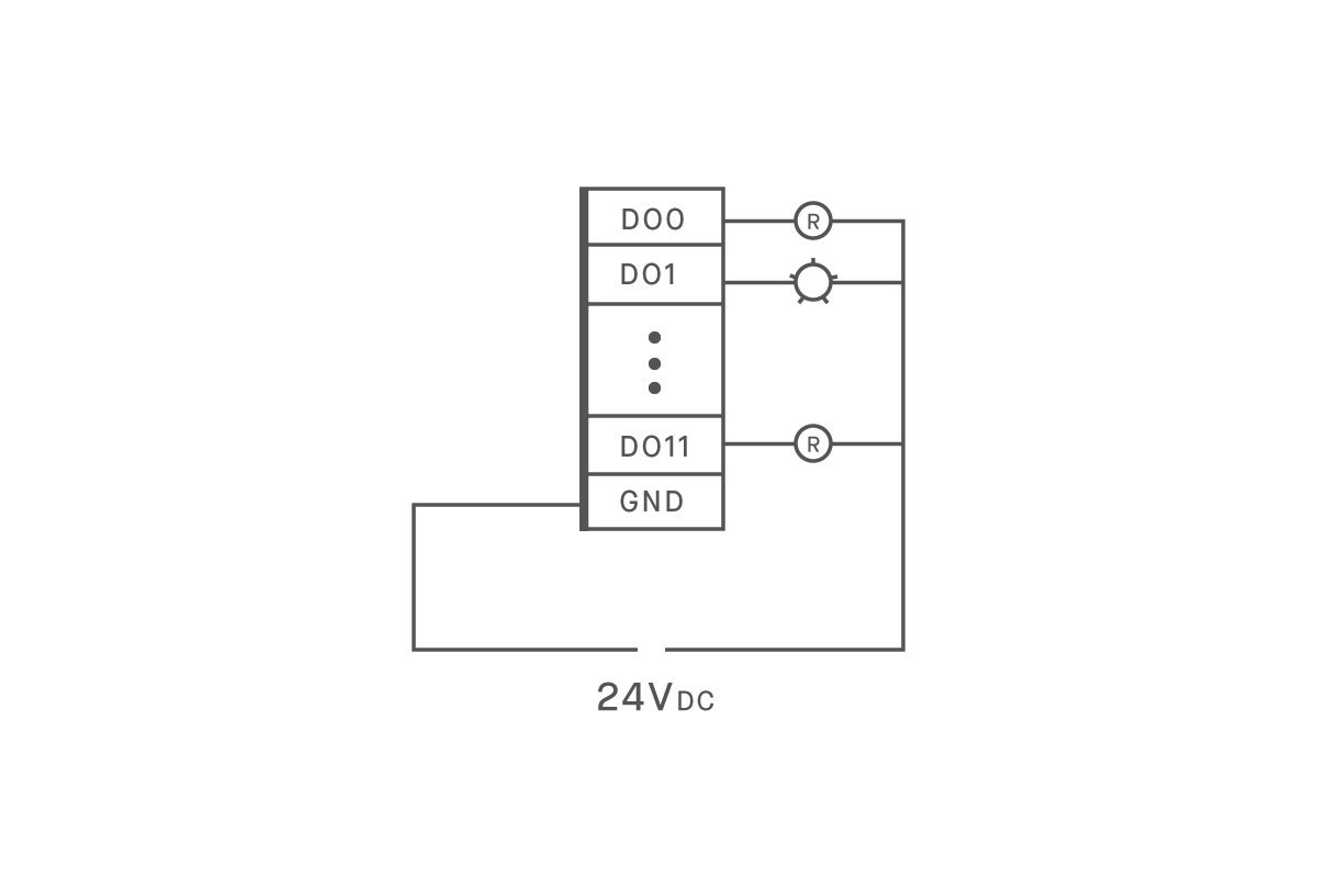
Sinking Output Configuration
Insert GND(-) wire into GND port
Supply 24V to opposite side of output device
When output is turned on, gateway will complete circuit and allow device to turn ON
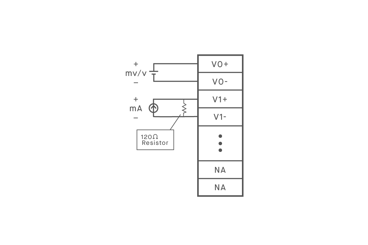
Analog Inputs
The analog inputs can be configured as a voltage or current input. This is done both on the hardware and in the cloud. On the hardware side, there is a tab that can be pulled outward (it will have this diagram on it). Behind the tab will be an array of dip switches. The out-of-box configuration for these switches is voltage (V). Simply move the switch into the opposite position to change the configuration to current (4-20mA).
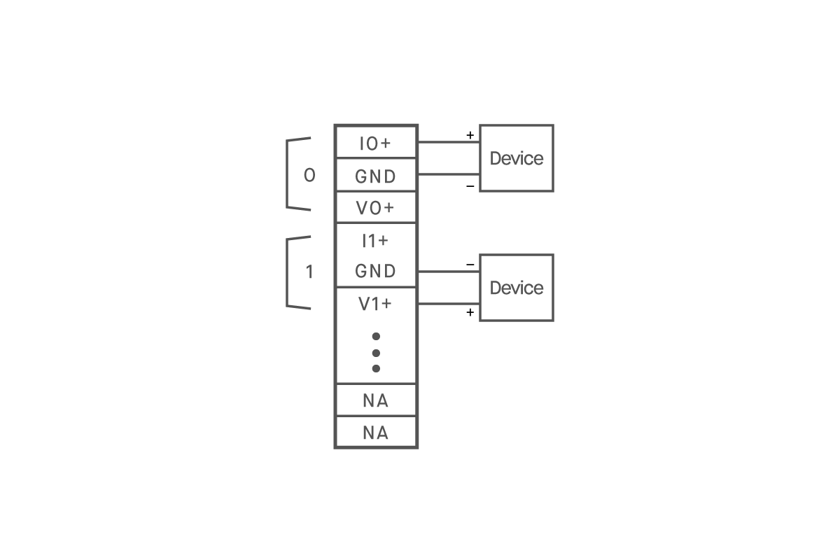
Three Wire Connection
Connect Sensor to power by placing (+) of sensor to (+) of power source
Connect the signal wire to V0+
Connect V0- to GND or (-) of the sensor or power source
Two Wire Connection
Connect Sensor to power by placing (+) of sensor to (+) of power source
Connect the (-) wire from the sensor to V0+ on the IG
Connect V0- to the GND or (-) of the power source
Multiple Devices connected to one signal
For Voltage Signals:
Devices can be connected in parallel
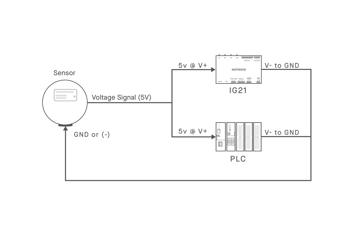
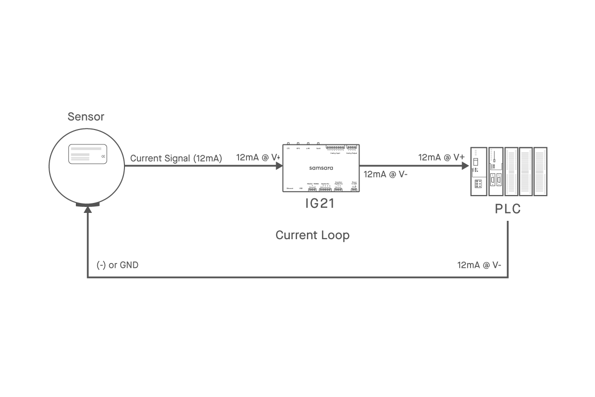
For Current Signals:
Devices must be connected In series
This means the signal from the sensor will be wired into V+ of device 1 then V- will be connected directly to V+ of device 2. V- of device 2 will then be connected to GND
This maintains a “current loop” and is required for this circuit to work
Analog Outputs
All output ports on this card can be voltage or current output depending on which ports are used. Dip switches are not needed to set configuration, simply wire and go.
Voltage Output
Connect V0+ to input of end device
Connect GND to GND or (-) of end device
Confirm cloud configuration is set to Voltage (see cloud configuration)
Current Output
Connect I0+ to input of end device
Connect GND to GND or (-) of end device
Confirm cloud configuration is set to Current (see cloud configuration)
Cloud Setup
Learn how to now set up the device in the cloud in the next article in this section