IG21 - Wire Analog and Digital IO
Summary
In this article, we will go through how to wire IO to your IG21.
Wire Digital IO
On the IG21, each digital IO terminal can be used as either an input or an output. We will review how to wire them in this article. This includes the counters digital IO terminals, though in the Samsara dashboard these are known as terminals 5 and 6.
In addition, it may be necessary to use a relay when wiring digital inputs, so we will walk through those steps as well.
Sourcing Inputs
On the IG21, the GND terminals are internally tied to the negative terminals. When wiring inputs, such as a switch, connect one end to the digital IO GND terminal and the other end to the desired input terminal.

Sinking Outputs
An output or "load", e.g. a light, is wired with one end connected to the positive power terminal and the other end to the desired output terminal.

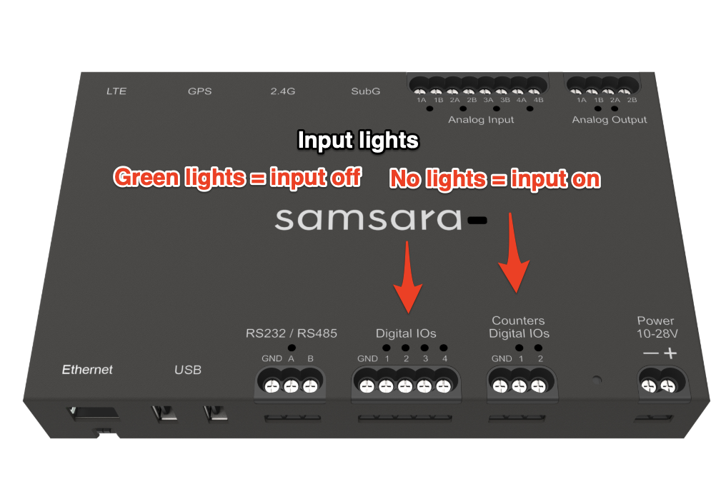
Digital I/O Lights
See what the lights mean below:
Wire a Relay to a Digital IO
At times it may be necessary to use a relay when wiring digital inputs. For example, an existing switch that you want to monitor may allow +24V to pass through it. Because the IG21's digital inputs activate when pulled low to 0V, you need a relay.
Wire a Relay to Digital Inputs
Wire the relay following the model below. Terminal labels and voltage of the relay may differ by manufacturer and use case, so make sure to study the circuit diagram accordingly.

Wire a Relay to Digital Outputs
Digital outputs require a relay when the load requires more voltage or current than the IG21 can provide.

Wire the relay following the model above. Terminal labels on the relay may differ by manufacturer so make sure to study the circuit diagram accordingly.
Wire Analog IO Sensors
You can wire your existing analog sensors to your IG to capture important data on your assets and operations. Whether your analog sensors output a 4-20mA or 0-10V signal, wiring to the IG21 will be the same. However, the exact wiring of the device depends on the number of wires needed.
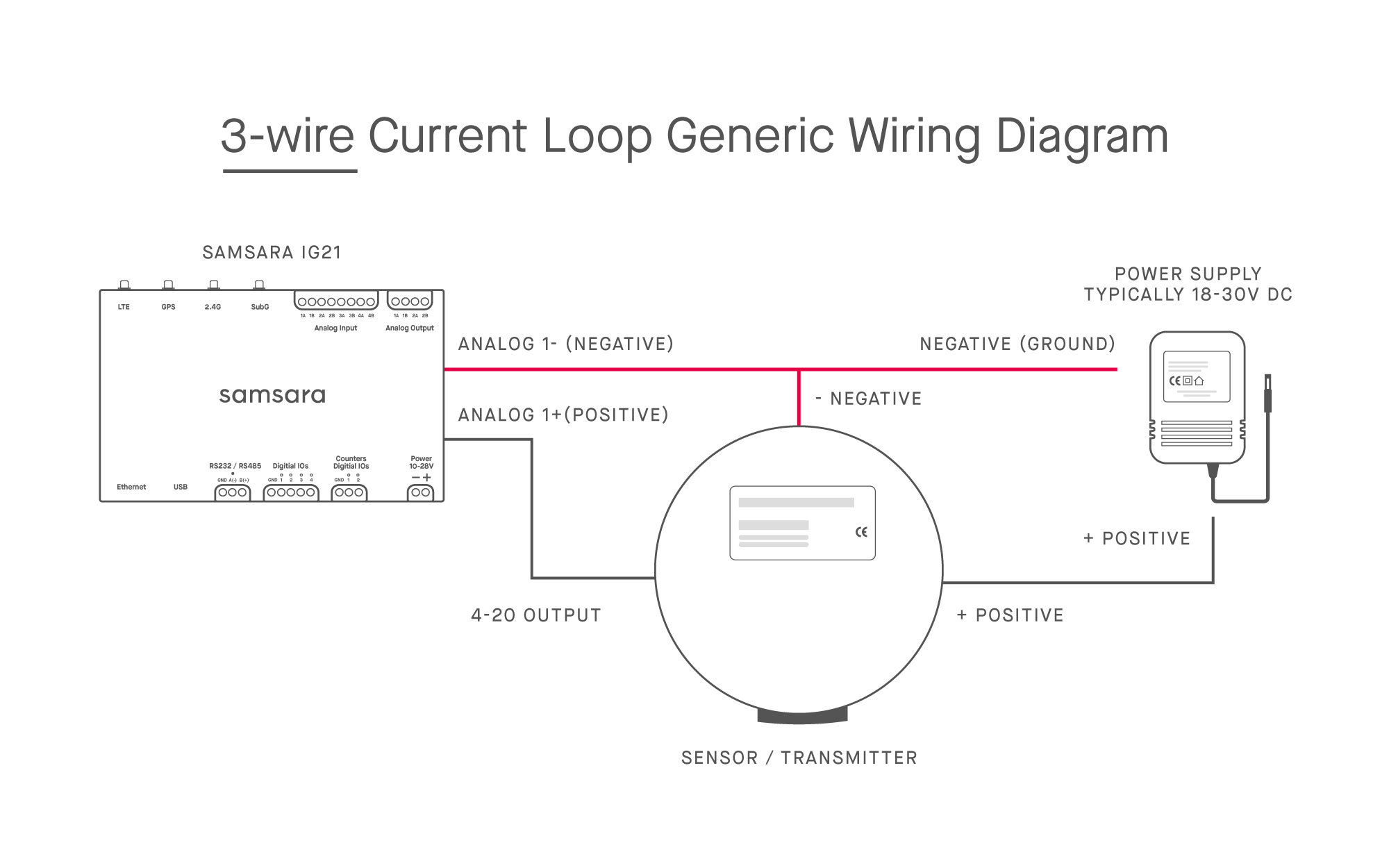
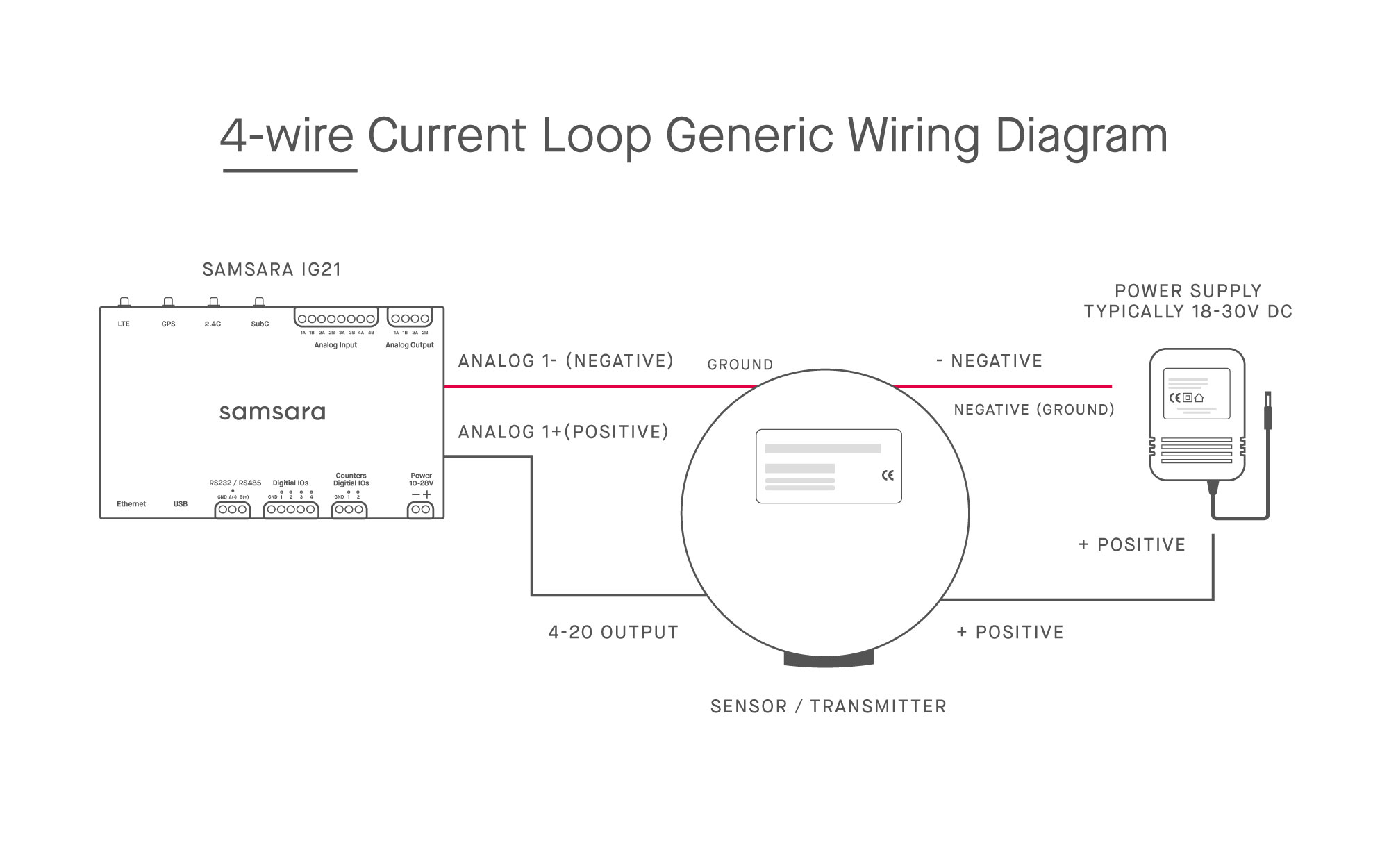
Analog IO Wiring Diagrams
The following images should be used as a model for your 2, 3, or 4-wire analog device:

Multiple Devices connected to one signal
For Voltage Signals
Devices can be connected in parallel

For Current Signals
Devices must be connected In series
This means the signal from the sensor will be wired into V+ of device 1 then V- will be connected directly to V+ of device 2. V- of device 2 will then be connected to GND
This maintains a “current loop” and is required for this circuit to work
Analog Outputs
All output channels can be voltage or current output depending on which configuration is specified in the cloud. Dip switches are not needed to set configuration, simply wire and go.
Voltage Output
Connect V0+ to input of end device
Connect GND to GND or (-) of end device
Confirm cloud configuration is set to Voltage
Current Output
Connect I0+ to input of end device
Connect GND to GND or (-) of end device
Confirm cloud configuration is set to Current
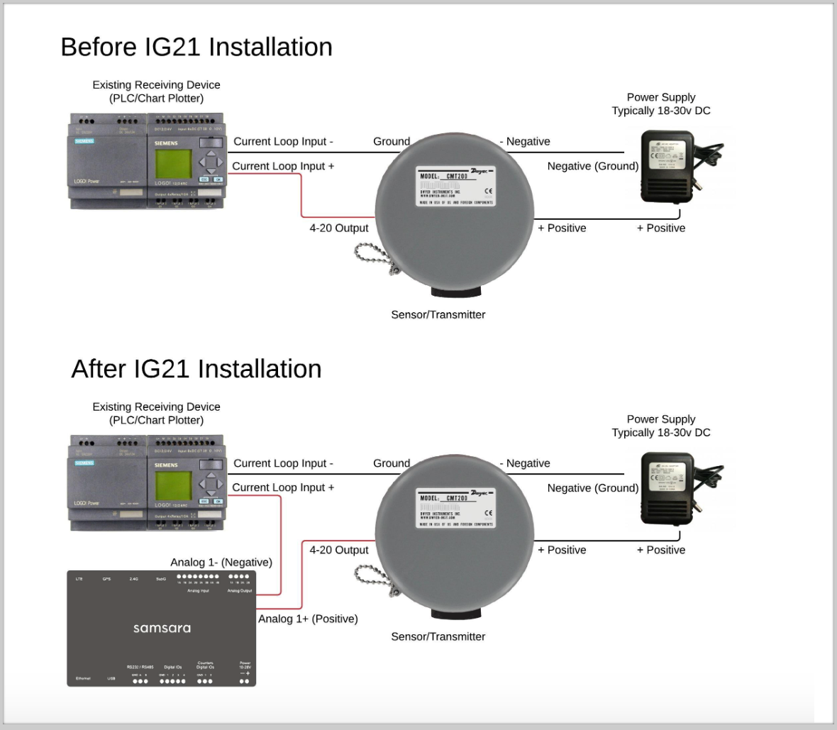
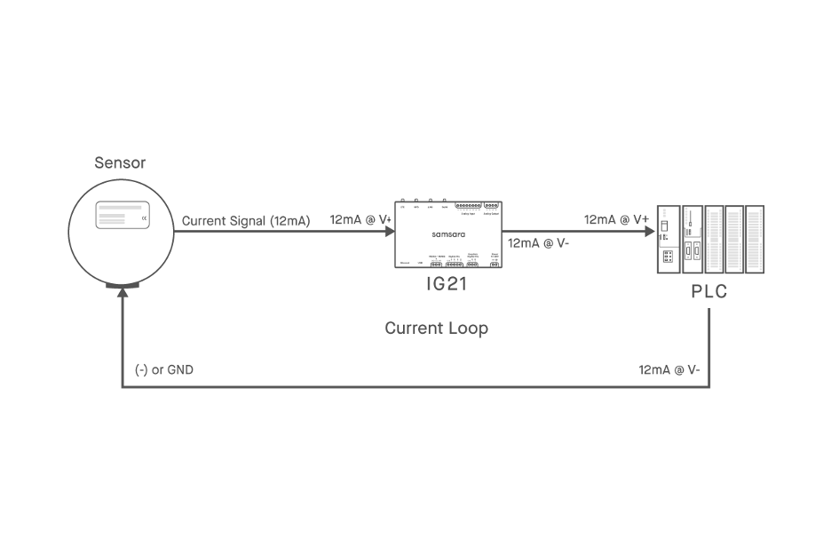
Add an IG21 to an Existing Loop
If you are using the IG21 to monitor analog inputs alongside an existing device, it must be installed inline with the existing current loop to accurately read and forward the values. This allows the PLC, Chart Recorder, etc. to continue its normal function while also providing the remote monitoring capabilities the IG21 excels in. Simply break the connection from the signal wire and rewire with the IG21 included as shown in the below image.